Cables, Wires
1. What are Cables and Wires?
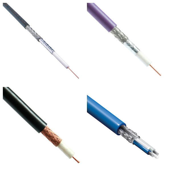
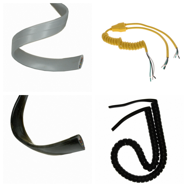
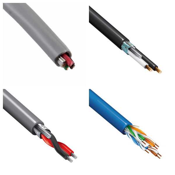
Cables: Made up of multiple individually insulated wires, the outer layer usually contains a protective layer, is used for power transmission, communication or signal transmission, and has a multi-conductor transmission function.
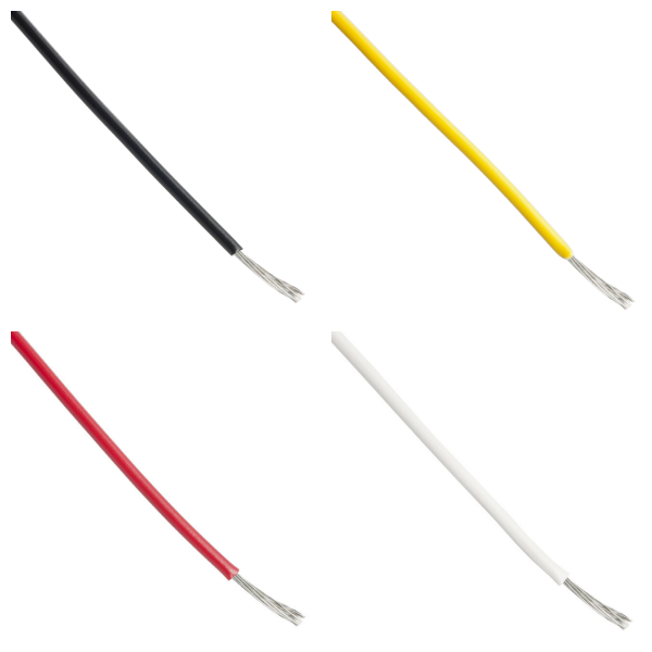
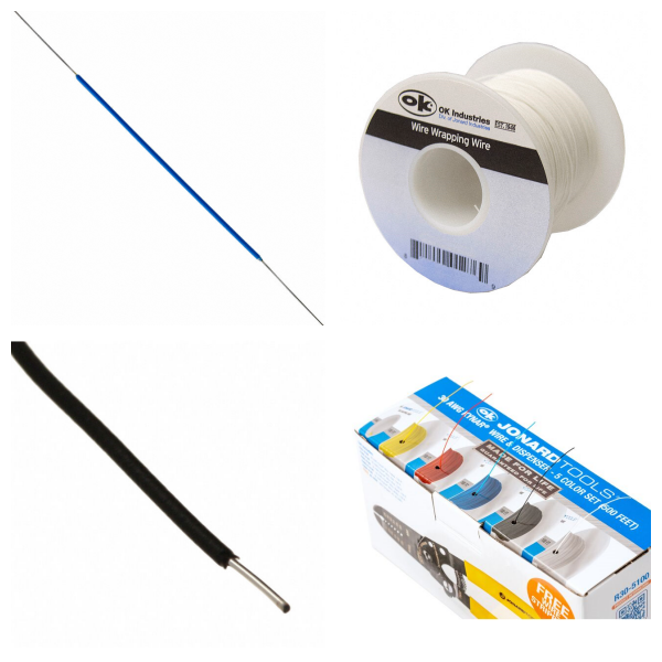
Wires: A single conductor (such as copper or silver), covered with an insulating material (such as plastic, rubber) on the outer layer, mainly used for low-power power or signal transmission.
2. What is the difference between Cables and Wires?
Structural Complexity: Cables are made up of multiple wires bundled with an additional protective layer, while wires are usually single conductors.
Application Scenarios: Wires are suitable for simple circuit connections; cables are mostly used in high-traffic scenarios, such as industrial control, fiber optic communications, etc..
3. What are the Key Parameters of Cables and Wires?
Bandwidth: Transmission capacity, measured by bit rate (bit rate, the number of bits transmitted per second).
Latency: The time it takes for data to travel from the sender to the receiver.
4. What are the Types of Cables and Wires?
1)Classification By Material: including PVC, rubber, halogen-free cables, etc.
2)Classification By Function:
Flame-retardant Cable: can limit the spread of fire, suitable for scenarios with high safety requirements.
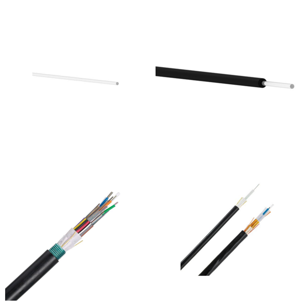
Fiber-optic Cable: used for high-speed data transmission.
5. What are Cables and Wires Used for?
Industry: factory automation, solar equipment. Communication: fiber-optic communication, telecommunication network.
Consumer Electronics: medical equipment, automotive electronics, IT infrastructure.
6. What are the Standards and certification of Cables and Wires?
Must comply with international cable standards such as UL, Japanese standard/Taiwan standard.
7. Cables and Wires FAQs
1) What are the Main Types of Cables and Wires?
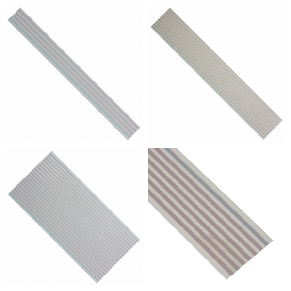
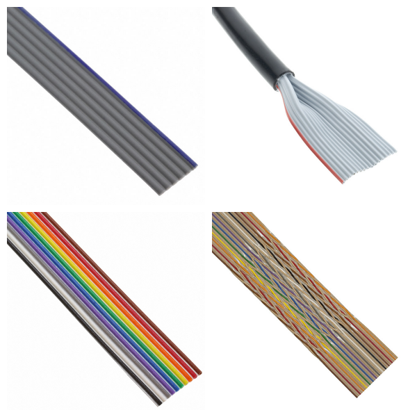
Power/Signal Transmission Cables: including power cables, and data cables (such as Cat5e, Cat6, Cat7).
Special Cables: such as AV cables, optical fibers, and military cables (for defense equipment).
Industrial Cables: such as cable sleeves, and cables for shrink wrap sealers.
2) How to Choose the Right Cable?
Network Performance Requirements: Cat5e is suitable for Gigabit Ethernet, and Cat6/Cat7 supports higher bandwidth and anti-interference.
Environmental Adaptability: The power cord needs to match the power capacity and connector specifications of the device; military scenarios require high-durability materials.
Cost and Quality: Copper-clad aluminum (CCA) conductors are cost-effective, but pure copper has better conductivity.
3) What are the Installation Precautions for Cables and Wires?
Make sure the power cord connector is compatible with the device interface to avoid power overload.
Use heat shrink tubing or professional sealers to improve cable insulation and protection levels.