
New title

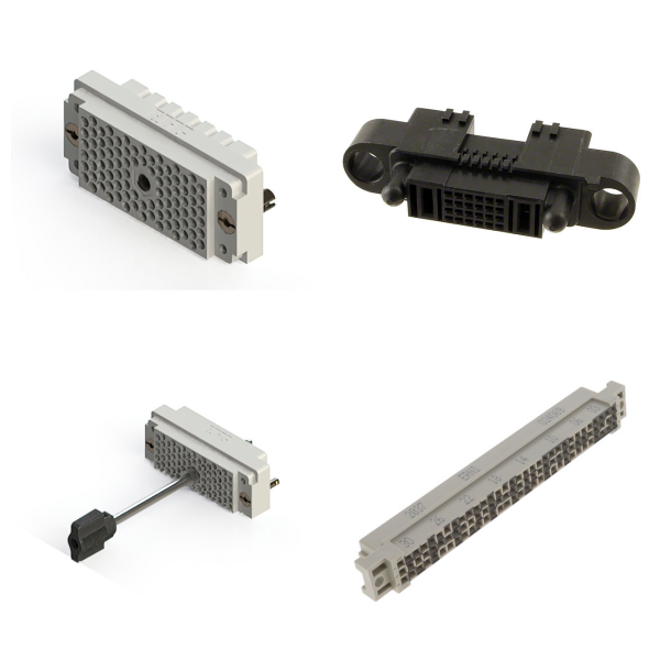
<h1> ARINC </h1> <p> ARINC (Aeronautical Radio, Incorporated) backplane connectors are used in high reliability applications in the aviation, airport, defense, government, healthcare, network, security, and transportation industries. ARINC developed the standards for the trays and boxes used to hold standard line-replaceable units (like radios) in aircraft, allowing electronics to be rapidly replaced without complex fasteners or test equipment. The backplane connectors are selected by their features, shell style and size, class code, and cavity type (A-F). Cavity type may include open, A524, 13W2, 57, 100, and 150. </p> <p>
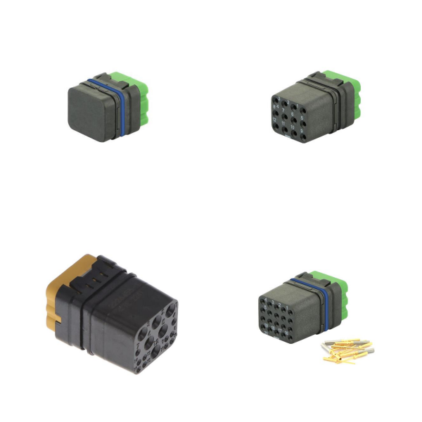
<h1> ARINC Inserts </h1> <p> ARINC connectors are based on standards developed by Aeronautical Radio Incorporated for aviation electronics and similar applications requiring high-reliability, blind-mating interconnect systems to enable rapid in-field replacement of faulty equipment. They are modular or configurable in character, allowing various configurations of electrical and fiber optic contact inserts to be assembled into standardized frames in order to construct a connector suited to a particular need. </p> <p>
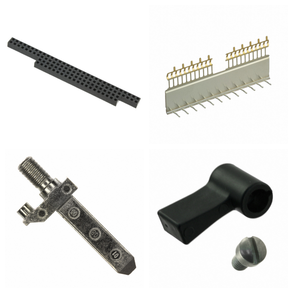
<h1> Backplane Connector Accessories </h1> <p> Backplane connector accessories are items used with backplane connector systems, which serve ancillary functions such as sealing of a connector assembly, mechanical fixation, avoidance of accidental un-mating, protection of un-mated connectors, cable strain relief, keying to reduce the chance of improper connection, handles, and others. </p>
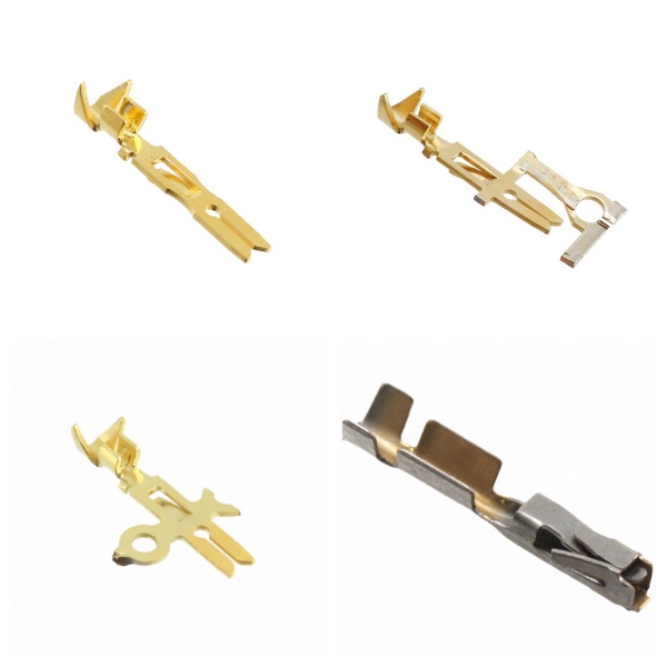
<h1> Backplane Connector Contacts </h1> <p> Backplane Connector Contacts are male or female terminals used in connectors. These terminals are specifically used in connectors that are designed for board or panel mount systems where other circuit boards may be plugged into them. The contact types are coaxial, fiber optics, ground, power, and signal with a contact termination of crimp and solder, press-fit, quick connect, screw mount, solder cup/eyelet, swage mount, and wire wrap. </p> <p>
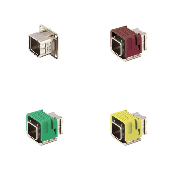
<h1> Backplane Connector Housings </h1> <p> Backplane connectors are used in high reliability applications such as computer buses and often employ secure fastening hardware for board, free hanging, through-hole, and panel mounting depending on the contact used. Connector housings do not include contacts or additional features such as shielding and backshells. They are differentiated by contact pitch, number of position and rows, connector type, and style. </p> <p>
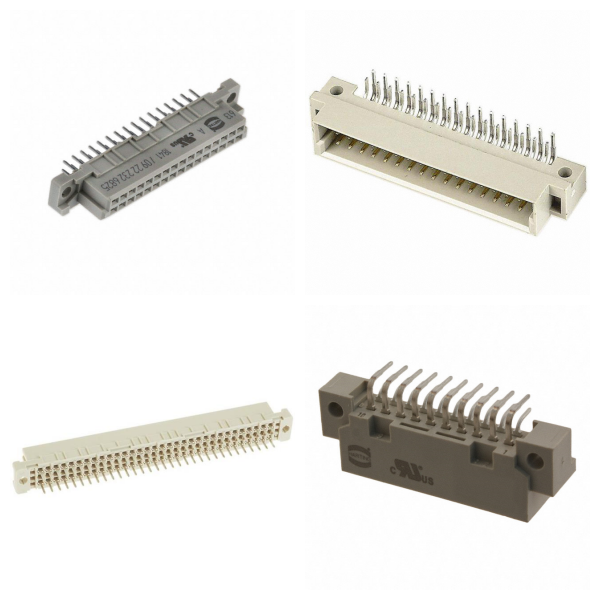
<h1> DIN 41612 </h1> <p> The DIN (Deutsches Institut für Normung, or German institute for standardization) 41612 standard defines a series of rectangular format electrical connectors known for use in card-and-rack style modular systems in information technology and similar equipment, where a blind mateable connector is needed for use in a relatively benign operating environment. </p> <p>
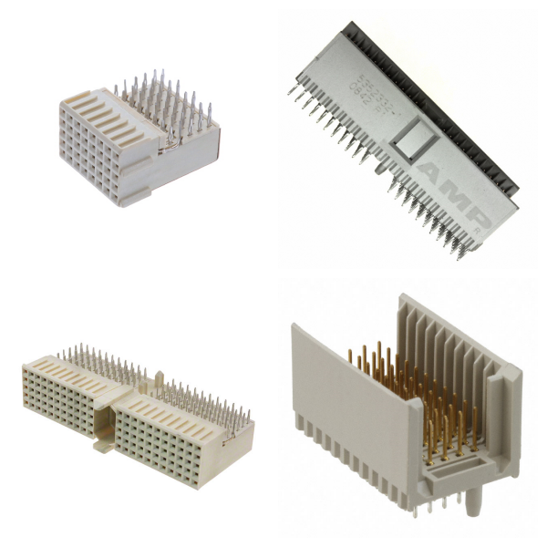
<h1> Hard Metric, Standard </h1> <p> Hard Metric, Standard Backplane Connectors conform to a set of specifications for interconnection devices. These devices are used in board or panel systems where other circuit boards can be plugged into. These connectors usually have a 2.0 mm pitch from row to row and column to column. The number of positions range from 3 (Power) to 308 (220 + 88 Ground) in Pitch dimensions 0.050” (1.27 mm), 0.071” (1.80 mm), 0.079” (2.00 mm), 0.150” (3.81 mm), or 0.295” (7.50 mm). </p> <p>
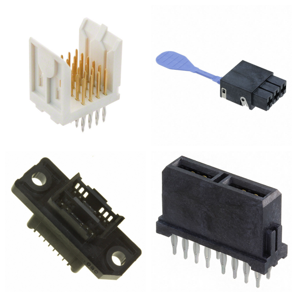
<h1> Specialized </h1> <p> Specialized Backplane Connectors conform to a set of specifications for use with daughterboards, midplane, coplanar, or front boards, and are meant to be used in a backplane or rack and panel system. They are characterized by the connector type, number of positions, pitch, number of rows, and contact layout. </p> <p>

Backplane Connectors

As a key component in the field of electronic components, backplane connectors play the core circuit connection and signal transmission functions in complex electronic devices.


1. What are Backplane Connectors?‌

Backplane connectors are vertical structure connectors used to connect daughter cards to backplanes, usually in a 90-degree orthogonal layout to achieve high-speed signal transmission between circuit boards. Its core functions include:


‌High-speed Signal Transmission‌: Supports differential signal or single-end signal transmission, with a rate of up to 25 Gbps to 224 Gbps;


‌High Current Carrying‌: Provides stable power support for high-performance servers, communication equipment, etc.;


‌Modular Expansion‌: Simplifies the complexity of the internal layout of equipment through flexible structural design (such as board-to-board, board-to-cable, etc.).


2. What are the Types of Backplane Connectors?‌

Backplane connectors are mainly divided into four categories according to their structure:


‌180° board-to-board (Backplane): suitable for high-density connection scenarios;


90° orthogonal board-to-board (Orthogonal): saves space and is often used in compact devices;


‌Board-to-Cable: connects circuit boards with external cables;

‌Cable-to-Cable: directly connects two cables.


Some special scenarios also support ‌floating installation‌ design, allowing ±0.2mm displacement to meet blind plug requirements.


3. ‌Technology Evolution and Industry Standards of Backplane Connectors‌

With the surge in bandwidth demand for AI servers and data centers, the transmission rate of backplane connectors continues to break through:

‌Rate Development‌: International leading manufacturers (such as Amphenol and Molex) have mass-produced 224Gbps products, supporting 67GHz bandwidth;

‌Technical Solution‌: Use PAM4 modulation technology to optimize signal integrity, and reduce PCB routing loss through near-chip installation (Near-chip) or overpass on chip bridging (Overpass on chip);

‌Industry Standards‌: Although there is a lack of unified specifications, Amphenol's technical parameters are often used as an industry reference.


4. What are Backplane Connectors Used for?‌

Backplane connectors are widely used in scenarios with strict requirements on stability and transmission efficiency:

‌AI Servers and Supercomputing‌: support massive data interaction between GPU clusters;

‌Communication Base Stations and Industrial Equipment‌: ensure the reliability of high-speed signal transmission;

‌High-end Storage Systems‌: achieve multi-module collaborative operation.


5. What are the ‌Installation Methods of Backplane Connectors?‌

Depending on the equipment requirements, a variety of installation options can be used:


‌Fixed Installation‌: fixed to the panel by screws (front/back installation);

‌Printed Board Installation‌: directly integrated into the PCB board;

‌Crimp Installation‌: use fisheye terminals to achieve conductive connection.


As the "super artery" of data transmission, the high-frequency performance and structural design of the backplane connector continue to promote the evolution of electronic devices to higher integration and efficiency. With the popularization of AI and cloud computing technologies, its market size is expected to maintain rapid growth.