New title

<h1> Crystal, Oscillator, Resonator Accessories </h1> <p> Crystal, Oscillator, and Resonator Accessories are supporting items to complete/work in accordance with products used as sources or references for frequency generation and time measurement. Accessory types include insulators, sockets, and more. This category can be filtered by for use with or related products, number of positions, package size accepted, and more. </p> <p>
<h1> Crystals </h1> <h2> 1. Crystals Overview‌ </h2> <p> Crystals (crystal resonator) is a passive electronic component based on quartz crystal, which generates an oscillation signal of precise frequency through the natural electromechanical effect of quartz crystal. Its main function is to provide clock signals for digital circuits and control the timing operation of the system. It is often likened to the "heart of electronic circuits". </p> <p>   </p> <h2> 2. What are the Types of Crystals?‌ </h2> <p> <strong>‌Passive Crystal Oscillator (Crystals)</strong>: It needs to rely on external circuit drive, only quartz crystal slices and pins, and external capacitors and other components are required to form a resonant circuit. </p> <p> <strong>‌Active Crystal Oscillator (Oscillator)</strong>: Integrated oscillation circuit, directly outputs stable square wave signal, no additional drive required. </p> <p>   </p> <h2> 3. How do Crystals Work?‌ </h2> <p> <strong>Using the piezoelectric effect of quartz crystal</strong>: When an alternating electric field is applied, the crystal will generate mechanical vibrations, thereby outputting an oscillation signal of a specific frequency. Its frequency range is usually from a few kHz to tens of MHz, and the frequency can be fine-tuned by adjusting the external load capacitor. </p> <p>   </p> <h2> 4. What are the ‌Structural Features of Crystals?‌ </h2> <p> <strong>‌Packaging Form‌</strong>: Common small packages, such as HC-49U, only contain crystal slices and pins. </p> <p> <strong>‌Circuit Dependency‌</strong>: It needs to work with external capacitors (usually 10-22pF) and oscillation circuits to work properly. </p> <p> <strong>‌Stability‌</strong>: The temperature characteristics of quartz materials determine their frequency stability. Temperature compensation or constant temperature crystal oscillators need to be selected in high-precision applications. </p> <p>   </p> <h2> 5. What are Crystals Used for?‌ </h2> <p> Provide reference clock signals for microprocessors and digital circuits to ensure system timing synchronization. </p> <p>   </p> <p> Frequency generation modules in communication equipment, such as RF signal modulation and demodulation. </p> <p>   </p> <h2> 6.‌Technical Parameter Considerations for Crystals‌ </h2> <p> <strong>‌Frequency Accuracy‌</strong>: Indicators such as frequency difference adjustment and temperature frequency difference affect system performance. </p> <p> <strong>‌Load Capacitance Matching‌</strong>: It is necessary to select appropriate external capacitance values according to circuit design to ensure the accuracy of the resonant frequency. </p> <p>   </p> <h2> 7. Selection and Design Recommendations for Crystals </h2> <p> <strong>‌Low Power Consumption Scenarios‌</strong>: Passive crystal oscillators are preferred to simplify circuit design. </p> <p> <strong>‌High Stability Requirements‌</strong>: Active crystal oscillators or temperature compensation/constant temperature crystal oscillators are recommended to avoid frequency drift caused by environmental interference. </p> <p> <strong>‌High Frequency Applications‌</strong>: It is necessary to pay attention to the crystal oscillator bandwidth and quality factor (Q value) to ensure signal purity. </p> <p>   </p> <h2> 8. Crystals FAQs </h2> <h3> 1) ‌How to choose a suitable nonlinear optical crystal? ‌ </h3> <p> It is necessary to consider laser parameters (such as wavelength, power/energy, divergence angle) and crystal performance (such as transmittance, damage threshold, effective nonlinear optical coefficient, phase matching type, and angle). Different application scenarios need to match the spectral acceptance bandwidth and temperature stability of the crystal. </p> <p>   </p> <h3> 2) ‌How do crystals ensure accurate timing in electronic devices? ‌ </h3> <p> Crystals generate stable frequency signals through the piezoelectric effect. For example, tuning fork crystals generate electrical signals through mechanical vibrations. Their resonant frequency is controlled by geometry and material properties. This stability makes it a core component of timing circuits such as quartz clocks and communication modules. </p> <p>   </p> <h3> 3) ‌How to keep the crystal oscillator stable in PCB layout? ‌ </h3> <p> Shorten the wiring distance between the crystal and the chip to reduce interference; </p> <p> Avoid high-frequency signal lines close to the crystal area; </p> <p> Use ground planes to isolate noise; </p> <p> Choose a package design with low parasitic capacitance. </p> <p>   </p> <h3> 4) ‌Can the crystal oscillator operate outside the specified temperature range? ‌ </h3> <p> Exceeding the nominal temperature range may cause frequency drift or failure. Industrial and automotive grade crystals usually have a wider temperature adaptability range (such as -40°C to 125°C), but the limit parameters need to be confirmed according to the specific model manual. </p> <p>   </p> <h3> 5) What is the difference between AT-cut and SC-cut crystals? ‌ </h3> <p> <strong>‌AT-cut crystals‌</strong>: lower cost, frequency-temperature characteristics are cubic curves, suitable for conventional environments; ‌SC-cut crystals‌: better temperature stability, strong resistance to thermal shock, suitable for high-precision or extreme temperature scenarios. </p> <p>   </p> <h3> 6) ‌How does the crystal damage threshold affect the application? ‌ </h3> <p> The damage threshold determines the maximum laser power density that the crystal can withstand. If this value is exceeded, it will cause optical performance degradation or physical damage. In high-power applications, crystals with high damage thresholds (such as LBO, BBO) must be selected and combined with heat dissipation design. </p> <p>   </p> <h3> 7) ‌What is the future development trend of tuning fork crystals? ‌ </h3> <p> Smaller size (such as SMD packaging) to adapt to miniaturized devices; </p> <p> Low power design to extend battery life; </p> <p> Improve resistance to vibration and environmental interference, and expand its application in the fields of Internet of Things, automotive electronics, etc. </p> <p>
<h1> Oscillators </h1> <h2> 1. Oscillators Overview‌ </h2> <p> An oscillator is an electronic component that converts DC power into a periodic AC signal. Its core function is to generate a stable and repeatable waveform (such as a sine wave, square wave, etc.) to provide a clock reference or frequency reference for the electronic system. </p> <p>   </p> <h2> 2. What are the Types of Oscillators?‌ </h2> <h3> 1) ‌By Working Principle‌: </h3> <p> ‌<strong>Harmonic Oscillator‌</strong>: Outputs a sine wave, relying on an LC resonant circuit or a crystal oscillator to achieve frequency stability. </p> <p>   </p> <p> <strong>‌Relaxation Oscillator‌</strong>: Outputs a square wave or sawtooth wave, and achieves frequency changes through capacitor charging and discharging. </p> <p>   </p> <h3> 2) ‌By Control Method‌: </h3> <p> <strong>‌Voltage-controlled Oscillator (VCO)</strong>: The frequency changes linearly with the input voltage, which is suitable for frequency modulation of communication systems. </p> <p> <strong>‌Temperature-compensated Oscillator (TCXO)‌ and ‌Oven-controlled Crystal Oscillator (OCXO)</strong>: Improve frequency stability through temperature compensation or constant temperature control. </p> <p>   </p> <h3> 3) ‌By Integration Form‌: </h3> <p> <strong>‌Active Crystal Oscillator‌</strong>: Contains an amplifier circuit and a crystal, and can directly output signals without an external circuit. </p> <p> <strong>‌Passive Resonator‌</strong>: requires an external clock circuit drive, often used in low-cost scenarios. </p> <p>   </p> <h3> 3. What is the ‌Structure of Oscillators?‌ </h3> <p> <strong>‌Core Components‌</strong>: quartz crystal (piezoelectric effect) or LC resonant circuit, with amplifier circuit and feedback network. </p> <p> <strong>‌Circuit Design‌</strong>: load capacitance (CL) and feedback resistance (Rf) need to match to achieve stable oscillation, and external components (such as current limiting resistors) can optimize signal quality. </p> <p>   </p> <h2> 4. What are the ‌Key Parameters of Oscillators?‌ </h2> <p> <strong>‌Frequency Accuracy‌</strong>: including initial frequency difference, temperature frequency difference, and aging rate. For high-precision scenarios, a crystal oscillator within ±1ppm should be selected. </p> <p> <strong>‌Phase Noise‌</strong>: measures signal purity, especially critical in RF applications. </p> <p> <strong>‌Load Capacitance‌</strong>: directly affects the oscillation frequency and must be consistent with the recommended value in the specification. </p> <p>   </p> <h2> 5. What are Oscillators Used for?‌ </h2> <p> <strong>‌Communication System‌</strong>: RF module, VCO in the frequency synthesizer. </p> <p> <strong>‌Digital Equipment‌</strong>: microprocessor clock source, memory timing control. </p> <p> <strong>‌Industrial and Medical‌</strong>: sensor signal conditioning, precision instrument timing. </p> <p>   </p> <h2> 6. Technology Trends of Oscillators </h2> <p> <strong>High Frequency</strong>: 5G/6G communication drives the demand for GHz-class high frequency oscillators. </p> <p> <strong>Integration</strong>: Multi-frequency output and low-power design are gradually becoming mainstream. </p> <p>   </p> <h2> 7. Oscillators FAQs </h2> <h3> 1) What are the main types of oscillators? </h3> <p> <strong>RC Oscillator</strong>: Uses an RC network to achieve frequency selection and phase shifting, suitable for the audio range. </p> <p> <strong>LC Oscillator</strong>: Based on the LC resonant circuit, commonly used in high-frequency scenarios. </p> <p> <strong>Crystal Oscillator</strong>: Uses a quartz crystal to control frequency, divided into passive (such as Pierce, Colpitts oscillators) and active. </p> <p> <strong>MEMS Oscillator</strong>: Based on a micro-electromechanical system, programmable, and with excellent anti-EMI performance. </p> <p> <strong>DDS (Direct Digital Synthesizer)</strong>: Generates frequency signals through digital control, commonly used in high-precision scenarios. </p> <p>   </p> <h3> 2) What is the difference between passive crystal oscillators and active crystal oscillators? </h3> <p> Passive oscillators need to rely on external circuit drive, while active oscillators have built-in drive circuits and can directly output signals. </p> <p>   </p> <h3> 3) How to choose the right oscillator? ‌ </h3> <p> <strong>Frequency Stability</strong>: expressed in ppm (parts per million), temperature stability is the key indicator. </p> <p> <strong>Output Type</strong>: match the requirements of downstream devices (sine wave, square wave, or clipped sine wave). </p> <p> <strong>Phase Noise and Jitter</strong>: affect the quality of high-frequency signals and need to be optimized according to the application scenario. </p> <p> <strong>Anti-interference Ability</strong>: MEMS oscillators are more tolerant to electromagnetic interference (EMI) than traditional quartz oscillators. </p> <p> <strong>Packaging and Environmental Adaptability</strong>: Small packages may lead to performance limitations, and size and stability need to be balanced. </p> <p>   </p> <h3> 4) What are the operating temperature range limitations of crystal oscillators? ‌ </h3> <p> Operating beyond the range may cause frequency drift or failure, and models that meet temperature specifications need to be selected. </p> <p>   </p> <h3> 5) How to optimize PCB layout to keep the oscillator stable?  </h3> <p> ‌Shorten signal trace length, reduce parasitic capacitance, and follow Pierce oscillator design guidelines (such as reasonable selection of load capacitance). </p> <p>   </p> <h3> 6) What factors affect the startup time of the oscillator? ‌ </h3> <p> It is mainly related to circuit design, load capacitance, and crystal characteristics. The typical startup time is in milliseconds. </p> <p>   </p> <h3> 7) ‌What is the "G sensitivity" of a crystal oscillator? ‌ </h3> <p> It refers to the frequency deviation caused by vibration or impact. Low G sensitivity devices should be selected for high-precision scenarios. </p> <p>   </p> <h3> 8) ‌How does aging affect the oscillator? ‌ </h3> <p> After long-term use, the frequency may slowly shift due to factors such as material stress. Regular calibration or selection of low aging rate models is required. </p> <p>
<h1> Pin Configurable/Selectable Oscillators </h1> <h2> 1. What are Pin Configurable/Selectable Oscillators? </h2> <p> Configurable selectable oscillators are oscillators that can be configured to a specific output frequency. They are available in both analog and digital forms and can be programmed to output a specific frequency or frequency range. </p> <p>   </p> <p> The frequency can be adjusted by replacing components within the oscillator or by using a frequency selection circuit. Configurable selectable oscillators typically have frequencies ranging from a few kHz to several GHz. These oscillators can be used in a variety of applications such as frequency control, clock generation, timing, and synchronization. </p> <p>   </p> <h2> 2. How do Pin Configurable/Selectable Oscillators Work? </h2> <p> The pins on the oscillator can be set to adjust the frequency, stability, and other characteristics of the oscillator. By adjusting the pins on the oscillator, different frequencies, output levels, and stability can be achieved depending on the application requirements. </p> <p>   </p> <h2> 3. What are Pin Configurable/Selectable Oscillators Used for? </h2> <p> ‌<strong>Multi-protocol Interface Clock Source</strong>‌ </p> <p> Dynamic clock adaptation of interfaces such as USB 2.0/3.0, PCIe Gen1-Gen4, etc. </p> <p>   </p> <p> <strong>‌FPGA/CPLD Configuration System</strong>‌ </p> <p> Boot mode selection through dedicated configuration pins (such as Bank14/Bank15) </p> <p>   </p> <p> <strong>‌Low-power Devices</strong>‌ </p> <p> Switch to a 32.768KHz low-frequency clock through pin control in sleep mode </p> <p>   </p> <p> <strong>Pin Configurable/Selectable Oscillators FAQs</strong> </p> <h2> ‌1. How to configure the oscillator through pins? ‌ </h2> <p> <strong>‌Level Selection‌</strong>: Select the preset frequency by pulling up/down the specified pin (such as CLK_SEL0, CLK_SEL1). </p> <p> <strong>‌Combinational Logic‌</strong>: Multiple pins form binary encoding to support more frequency options (for example, 2 pins can provide 4 combinations). </p> <p> <strong>‌Note‌</strong>: Refer to the data sheet to confirm the pin level requirements (such as TTL/CMOS voltage). </p> <p>   </p> <h2> ‌2. What frequency options do pin configurable/selectable oscillators support? ‌ </h2> <p> <strong>The supported frequency range and options vary by device. Common configurations include</strong>: </p> <p> <strong>Basic Mode</strong>: low speed (32.768 kHz) for low power consumption, high speed (8 MHz~100 MHz) for main clock. </p> <p> <strong>Extended Mode</strong>: Some devices support fractional division or multiplication (such as PLL bypass mode). </p> <p> <strong>‌Key Parameters‌</strong>: frequency tolerance (±0.5%~±5%), temperature stability (±10 ppm~±100 ppm). </p> <p>   </p> <h2> ‌3. What should be paid attention to when switching the frequency of the pin configurable/selectable oscillator? ‌ </h2> <p> <strong>‌Voltage Stability‌</strong>: Ensure that there is no fluctuation in the power supply during switching to avoid an accidental reset. </p> <p> <strong>‌Timing constraints‌</strong>: Some devices require pin configuration after reset, or wait for the clock to stabilize before switching. </p> <p> <strong>‌Transient Interference‌</strong>: High-speed switching may cause EMI. It is recommended to add filter capacitors or series resistors. </p> <p>   </p> <h2> ‌4. What are the typical application scenarios of a pin configurable/selectable oscillator? ‌ </h2> <p> <strong>‌Dynamic Power Management‌</strong>: Switch to low-speed mode to reduce power consumption (such as battery-powered devices). </p> <p> <strong>‌Multi-protocol Compatibility‌</strong>: Adapt different clock rates for interfaces such as UART and SPI. </p> <p> <strong>‌Fault Recovery‌</strong>: Switch to backup oscillator when the main clock fails. </p> <p>   </p> <h2> ‌5. How to reduce electromagnetic interference (EMI) of pin configurable/selectable oscillators? ‌ </h2> <p> <strong>‌Layout Optimization‌</strong>: Shorten clock pin routing and keep away from analog signal paths. </p> <p> <strong>‌Shielding Measures‌</strong>: Surround clock lines with ground wires or use shielded cables. </p> <p> <strong>‌Slope Control‌</strong>: Enable oscillator slew rate limiting function (if any). </p> <p>   </p> <h2> 6. Does the pin configurable/selectable oscillator support dynamic switching during runtime? ‌ </h2> <p> <strong>‌Some Devices Support‌</strong>: Make sure that no critical tasks are running during the switching process (such as Flash writing). </p> <p> <strong>‌Sequential Operation‌</strong>: Switch to intermediate frequency (such as PLL bypass) first, then switch to target frequency. </p> <p> <strong>‌Asynchronous System Risk‌</strong>: It may cause peripheral (ADC, timer) timing errors and needs to be reinitialized. </p> <p>
<h1> Programmable Oscillators </h1> <h2> 1. Programmable Oscillators Overview </h2> <p> A programmable oscillator is a clock generator that can adjust output frequency, waveform, and other parameters through software or hardware configuration. Its core consists of a quartz crystal or ceramic resonator and a signal conditioning circuit. Compared with traditional fixed-frequency oscillators, its advantages are: </p> <p>   </p> <p> <strong>Flexibility and Configurability</strong>: Users can dynamically adjust parameters such as frequency, voltage, and output format (such as square wave, sine wave) according to their needs; </p> <p> <strong>High Precision and Stability</strong>: Built-in compensation circuit optimizes frequency stability (typical value can reach ±25ppm~±50ppm); </p> <p> <strong>Various Interface Support</strong>: Compatible with LVDS, HCMOS, LVPECL, and other output formats, adapting to different digital system requirements. </p> <p>   </p> <h2> 2. What are the Types of Programmable Oscillators? </h2> <p> <strong>By Material</strong>: quartz-based (high frequency, high stability) or ceramic-based (low cost, low power consumption); </p> <p> <strong>By Function</strong>: standard clock oscillator, frequency synthesizer type, temperature compensation type, etc. </p> <p>   </p> <h2> 3. What are the Key Parameters of Programmable Oscillators? </h2> <table> <tbody> <tr class="firstRow"> <td width="177" valign="top" style="padding: 0px 7px; border-width: 1px; border-color: windowtext; background: rgb(190, 190, 190);"> <p> Parameter </p> </td> <td width="391" valign="top" style="padding: 0px 7px; border-width: 1px; border-color: windowtext; background: rgb(190, 190, 190);"> <p> Typical Range/Option </p> </td> </tr> <tr> <td width="177" valign="top" style="padding: 0px 7px; border-left-width: 1px; border-left-color: windowtext; border-right-width: 1px; border-right-color: windowtext; border-top: none; border-bottom-width: 1px; border-bottom-color: windowtext;"> <p> Frequency Range </p> </td> <td width="391" valign="top" style="padding: 0px 7px; border-left-width: 1px; border-left-color: windowtext; border-right-width: 1px; border-right-color: windowtext; border-top: none; border-bottom-width: 1px; border-bottom-color: windowtext;"> <p> 1MHz~800MHz (partially supports GHz level) </p> </td> </tr> <tr> <td width="177" valign="top" style="padding: 0px 7px; border-left-width: 1px; border-left-color: windowtext; border-right-width: 1px; border-right-color: windowtext; border-top: none; border-bottom-width: 1px; border-bottom-color: windowtext;"> <p> Frequency Stability </p> </td> <td width="391" valign="top" style="padding: 0px 7px; border-left-width: 1px; border-left-color: windowtext; border-right-width: 1px; border-right-color: windowtext; border-top: none; border-bottom-width: 1px; border-bottom-color: windowtext;"> <p> ±25ppm ~ ±100ppm </p> </td> </tr> <tr> <td width="177" valign="top" style="padding: 0px 7px; border-left-width: 1px; border-left-color: windowtext; border-right-width: 1px; border-right-color: windowtext; border-top: none; border-bottom-width: 1px; border-bottom-color: windowtext;"> <p> Power Supply Voltage </p> </td> <td width="391" valign="top" style="padding: 0px 7px; border-left-width: 1px; border-left-color: windowtext; border-right-width: 1px; border-right-color: windowtext; border-top: none; border-bottom-width: 1px; border-bottom-color: windowtext;"> <p> 1.8V~5V (low power or wide voltage design) </p> </td> </tr> <tr> <td width="177" valign="top" style="padding: 0px 7px; border-left-width: 1px; border-left-color: windowtext; border-right-width: 1px; border-right-color: windowtext; border-top: none; border-bottom-width: 1px; border-bottom-color: windowtext;"> <p> Package Type </p> </td> <td width="391" valign="top" style="padding: 0px 7px; border-left-width: 1px; border-left-color: windowtext; border-right-width: 1px; border-right-color: windowtext; border-top: none; border-bottom-width: 1px; border-bottom-color: windowtext;"> <p> SMD (such as SOT-23, QFN), DIP, etc. </p> </td> </tr> <tr> <td width="177" valign="top" style="padding: 0px 7px; border-left-width: 1px; border-left-color: windowtext; border-right-width: 1px; border-right-color: windowtext; border-top: none; border-bottom-width: 1px; border-bottom-color: windowtext;"> <p> Operating Temperature </p> </td> <td width="391" valign="top" style="padding: 0px 7px; border-left-width: 1px; border-left-color: windowtext; border-right-width: 1px; border-right-color: windowtext; border-top: none; border-bottom-width: 1px; border-bottom-color: windowtext;"> <p> -40°C ~ 85°C (industrial standard) </p> </td> </tr> </tbody> </table> <p>   </p> <h2> 4. What are Programmable Oscillators Used for? </h2> <p> <strong>Communication System</strong>: as the clock source of the RF module and baseband processing unit; </p> <p> <strong>Embedded System</strong>: provides an adjustable clock for programmable logic devices such as FPGA and CPLD; </p> <p> <strong>Test and Measurement Equipment</strong>: support instrument calibration and synchronization of multi-protocol interfaces; </p> <p> <strong>Industrial Control</strong>: real-time controller clock suitable for a wide temperature and high reliability environment. </p> <p>   </p> <h2> 5. Technology Trends of Programmable Oscillators </h2> <p> <strong>Integration</strong>: Integrate EEPROM storage technology to save configuration parameters during power-off and quickly load them; </p> <p> <strong>Low-power Design</strong>: Use CMOS technology to optimize dynamic power consumption and adapt to the needs of portable devices; </p> <p> <strong>Intelligent Calibration</strong>: Remote online frequency adjustment is achieved through digital interfaces (such as I²C and SPI). </p> <p>   </p> <p> Programmable oscillators have become one of the core components of modern electronic system design due to their flexibility and high reliability. When selecting a programmable oscillator, it is necessary to balance frequency accuracy, power consumption, and cost requirements based on specific scenarios. </p> <p>   </p> <p>
<h1> Resonators </h1> <h2> 1. Resonators Overview </h2> <p> The resonator is a device used to store or limit electromagnetic/acoustic energy, and achieves frequency control or energy resonance through the piezoelectric effect (such as quartz or ceramic) or specific structural design (such as an intake system). The core function is to stabilize frequency output, reduce interference, and improve energy efficiency in specific scenarios. It is a passive electronic component, which is mainly divided into two categories: </p> <p> <strong>‌Quartz Crystal Resonator</strong>‌ </p> <p> It uses the piezoelectric effect of quartz crystal to generate a high-precision resonant frequency, and the frequency stability is better than that of a ceramic resonator. Common packaging forms include DIP plug-in and SMD patch type. </p> <p>   </p> <p> <strong>‌Ceramic Resonator</strong>‌ </p> <p> It uses the piezoelectric effect of ceramic materials to achieve resonant frequency, which is low in cost but relatively weak in accuracy. </p> <p>   </p> <h2> 2. What are the Core Characteristics of Resonators? </h2> <p> <strong>‌Frequency Control</strong>‌ </p> <p> By adjusting the load capacitance or internal inductance/capacitance parameters, the operating frequency can be fine-tuned to near the nominal value. </p> <p>   </p> <p> <strong>‌Stability Parameters</strong>‌ </p> <p> ‌Temperature frequency difference‌: the maximum allowable deviation value of the frequency within the operating temperature range (such as ±10 ppm); ‌Aging rate‌: the long-term drift error of the frequency over time. </p> <p>   </p> <p> <strong>‌Impedance Characteristics</strong>‌ </p> <p> The load resonant resistance (RL) represents the equivalent resistance value when connected in series with the specified capacitor. </p> <p>   </p> <h2> 3. Difference between Resonators and Oscillators </h2> <p> <strong>‌Resonator‌</strong>: It needs to rely on an external circuit drive and only provides a frequency reference. It is a passive device. </p> <p> <strong>‌Oscillator‌</strong>: It integrates amplification and feedback circuits and can directly output stable oscillation signals. It is an active device. </p> <p>   </p> <h2> 4. What are Resonators Used for? </h2> <p> <strong>‌Wireless Communication System‌</strong>: It is used for RF signal filtering and frequency selection. </p> <p> <strong>‌Clock Circuit‌</strong>: Scenarios that require high-precision timing control, such as computer motherboards and microcontrollers (mainly quartz resonators). </p> <p> <strong>‌Industrial Control‌</strong>: High-frequency noise suppression in filter circuits (such as resonant reactors). </p> <p> <strong>‌Consumer Electronics‌</strong>: Ceramic resonators are often used in low-cost electronic devices (such as remote controls). </p> <p>   </p> <h2> 5. Selection and Use Precautions for Resonators </h2> <p> <strong>‌Load Matching‌</strong>: The load capacitance needs to match the circuit design to avoid frequency deviation. </p> <p> <strong>‌Environmental Adaptability‌</strong>: </p> <p> Quartz resonators need to pay attention to the temperature range (such as -40℃~85℃) and temperature compensation requirements; </p> <p>   </p> <p> Ceramic resonators need to prevent frequency drift caused by mechanical vibration. </p> <p>   </p> <p> ‌Aging Effect‌: Long-term use requires a reserve of aging rate tolerance. </p> <p>
<h1> Stand Alone Programmers </h1> <p> Stand Alone Programmers are a type of special equipment that can complete chip programming operations without relying on an external development environment or host computer. They are mainly used for offline burning and parameter configuration of programmable devices such as memory and microcontrollers. They are key tools to improve efficiency and flexibility in the fields of electronic manufacturing and equipment maintenance. </p> <p>   </p> <h2> 1. What are the Core Functions and Technical Features of Stand Alone Programmers? </h2> <p> ‌<strong>Independent Operation Capability‌</strong> </p> <p> No need to connect to a PC or other main control device, autonomous operation is achieved through the built-in processor and firmware. For example, when writing data to an EEPROM device (such as AT24C02), addressing and erase operations can be directly completed through a preset algorithm. </p> <p>   </p> <p> <strong>‌Multi-protocol Support</strong>‌ </p> <p> Compatible with mainstream communication protocols such as I²C, SPI, Microwire, etc., and adapts to chip programming requirements of different interfaces. For example, the 24C series EEPROM realizes device addressing and data transmission through the I²C bus. </p> <p>   </p> <p> <strong>‌Package Compatibility</strong>‌ </p> <p> Supports multiple packaging forms such as DIP, SOIC, QFP, etc., and the hardware design needs to match the pin layout and physical size of the target chip. For example, BGA packaged chips require customized adapters to ensure welding reliability. </p> <p>   </p> <h2> 2. What are Stand Alone Programmers Used for? </h2> <p> <strong>‌Memory Programming</strong>‌ </p> <p> For non-volatile memories such as EEPROM and Flash, parameter configuration, firmware burning, and data storage functions are realized. For example, calibration data is written in batches through an independent programmer in an embedded system. </p> <p>   </p> <p> <strong>‌Production Line Batch Operation</strong>‌ </p> <p> Applicable to factory automation production lines, supporting high-speed, multi-task parallel processing to improve production efficiency. </p> <p>   </p> <p> <strong>‌On-site Maintenance and Upgrade</strong>‌ </p> <p> No complex debugging environment is required, and chip programs can be updated or data errors can be repaired directly on the equipment site. </p> <p>   </p> <h2> 3. Technical Challenges and Development Trends of Stand Alone Programmers </h2> <p> <strong>‌High Compatibility Design</strong>‌ </p> <p> It is necessary to cope with the rapid iteration of chip models and expand the support range through modular hardware and updateable firmware. </p> <p>   </p> <p> <strong>‌Low Power Consumption and Portability</strong>‌ </p> <p> Optimize power management for mobile scenarios, integrate battery power solutions, and adapt to outdoor or temporary operation needs. </p> <p>   </p> <p> <strong>‌Intelligent Function Integration‌</strong> </p> <p> Introduce automatic verification algorithms and error detection mechanisms to ensure the integrity and reliability of burned data. </p> <p>   </p> <h2> 4. Typical Product Examples of Stand Alone Programmers </h2> <p> <strong>‌EEPROM Programmer‌</strong>: supports AT24C series chips, realizes data reading and writing through the I²C protocol, and adapts to the voltage range of 1.8V to 5V. </p> <p> <strong>‌Multi-protocol Universal Programmer‌</strong>: integrates SPI and I²C interfaces, is compatible with QFN, BGA, and other packages, and is suitable for offline programming of complex chips. </p> <p>   </p> <p>
<h1> VCOs (Voltage Controlled Oscillators) </h1> <p> VCOs (Voltage Controlled Oscillators) are electronic components that adjust the frequency of the output signal through the input voltage. Their core function is to convert voltage changes into frequency changes. </p> <p>   </p> <h2> 1. What is the Core Principle of VCOs (Voltage Controlled Oscillators)? </h2> <p> VCO consists of an oscillator (such as a multivibrator or crystal oscillator) and a voltage control circuit. It adjusts the parameters of the oscillation circuit (such as capacitance and inductance) by changing the input voltage to achieve frequency modulation. Typical implementation methods include using a varactor diode to adjust the capacitance value of the resonant circuit to change the oscillation frequency. </p> <p>   </p> <h2> 2. What are the Core Features of VCOs (Voltage Controlled Oscillators)? </h2> <p> <strong>‌Linearity‌</strong>: The output frequency and input voltage show a linear relationship to ensure the accuracy of control; </p> <p> <strong>‌Tuning Range‌</strong>: Supports adjustment within a wide frequency range to meet the needs of different scenarios; </p> <p> <strong>‌Stability‌</strong>: Use high-quality components and processes to ensure the low drift characteristics of the output frequency; </p> <p> <strong>‌Phase Noise‌</strong>: As a key indicator for high-frequency applications, it directly affects the signal quality. </p> <p>   </p> <h2> 3. What are VCOs (Voltage Controlled Oscillators) Used for? </h2> <p> <strong>Communication System</strong> </p> <p> Used in the local oscillator circuit in frequency synthesis, FM/AM broadcasting, and digital communication, supporting frequency hopping technology to achieve anti-interference and spectrum reuse; </p> <p> Realize signal modulation and demodulation in wireless transceiver equipment. </p> <p>   </p> <p> <strong>RF and Radar System</strong> </p> <p> Generate RF signals to achieve target detection and positioning, and enhance the system's anti-interference ability. </p> <p>   </p> <p> <strong>Audio and Test Equipment</strong> </p> <p> Generate variable frequency sound effects in music synthesizers; </p> <p> Used as a high-precision signal source for instrument testing, supporting flexible frequency band switching. </p> <p>   </p> <h2> 4. Technology Evolution of VCOs (Voltage Controlled Oscillators) </h2> <p> With the development of new materials and processes, VCO continues to improve in high-frequency band stability, phase noise optimization, and integration, expanding its application potential in emerging fields such as 5G communications and millimeter-wave radar. </p> <p>   </p> <h2> 5. VCOs (Voltage Controlled Oscillators) FAQs </h2> <h3> 1) What are the main parameters of ‌VCO? </h3> <p> <strong>‌Center Frequency‌</strong>: The reference frequency when there is no control voltage. </p> <p> <strong>Tuning Range‌</strong>: The frequency range that the VCO can output (such as 1GHz–2GHz). </p> <p> <strong>‌Voltage Control Sensitivity (Kvco)</strong>: The frequency offset caused by a unit voltage change (such as 100MHz/V). </p> <p> <strong>‌Phase Noise</strong>: A key indicator for measuring the short-term stability of a frequency signal (dBc/Hz). </p> <p> <strong>‌Tuning Linearity</strong>: The linear relationship error between the control voltage and the output frequency. </p> <p> <strong>‌Power Consumption and Size</strong>: Low power consumption and miniaturization are required in modern applications. </p> <p>   </p> <h3> 2) ‌How to optimize the linearity of the VCO? ‌ </h3> <p> <strong>‌Circuit Design Optimization</strong>: Use the Clapp oscillator structure to improve the Q value stability. </p> <p> <strong>‌Component Selection</strong>: Use varactor diodes or linear compensation circuits to reduce nonlinear errors. </p> <p> <strong>‌Calibration Technology</strong>: Correct the nonlinearity of the voltage-frequency curve through a digital compensation algorithm. </p> <p>   </p> <h3> 3) ‌How to reduce the phase noise of the VCO? ‌ </h3> <p> <strong>‌Component Quality</strong>: Use low-noise transistors and high-Q resonant components. </p> <p> <strong>‌Power supply filtering</strong>: Reduce the interference of power supply ripple on the oscillation circuit. </p> <p> <strong>‌Shielding and Layout</strong>: Optimize the PCB layout to reduce electromagnetic coupling noise. </p> <p>   </p> <h3> 4) What factors limit the tuning range of the VCO? ‌ </h3> <p> <strong>‌Varactor Diode Capacitance Variation Range‌</strong>: directly affects the upper limit of frequency tuning. </p> <p> <strong>‌Resonant Circuit Design‌</strong>: The topology of the LC or RC oscillator determines the tuning sensitivity. </p> <p> <strong>‌Process and Temperature‌</strong>: Semiconductor process deviations and ambient temperature changes may cause frequency drift. </p> <p>

Crystals, Oscillators, Resonators

Crystals, oscillators and resonators each have their own characteristics and different application scenarios. In actual design, frequency stability, power consumption, cost and environmental factors need to be considered comprehensively.

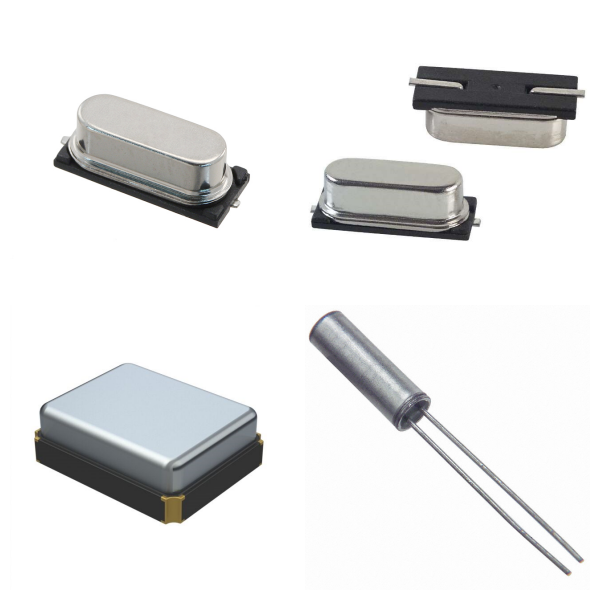
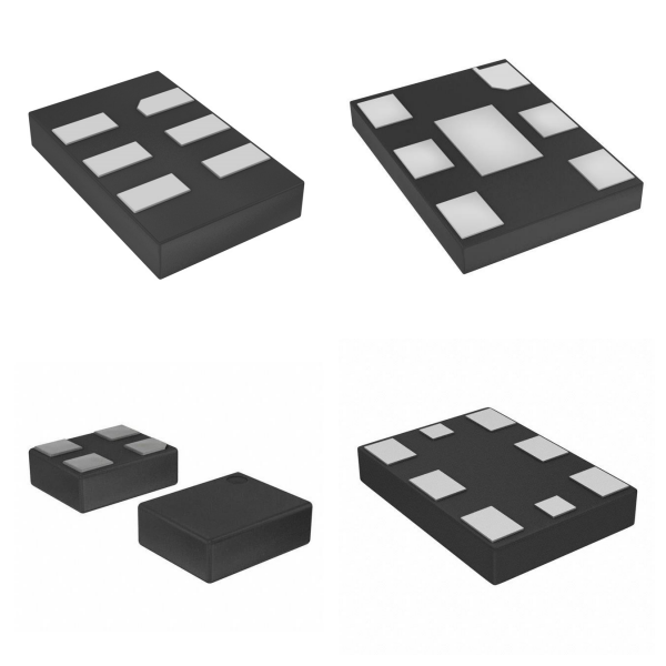
1. What are Crystals?

Definition: Crystals are typical passive devices (Passive Device), the main component of which is quartz (SiO₂), which use the piezoelectric effect to realize the mutual conversion of mechanical vibration and electrical signals.

‌Working principle‌: When an external voltage is applied, the crystal generates a resonant signal of a fixed frequency through mechanical vibration, but it does not have the driving ability itself and needs to rely on external circuits (such as amplifiers and load capacitors) to maintain oscillation.

‌Application scenario‌: Commonly used in clock circuits (such as microcontrollers and communication equipment) to provide reference frequency, and the nominal frequency range covers kHz to MHz (such as 32.768kHz or 24MHz).

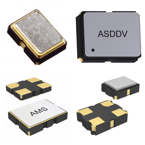
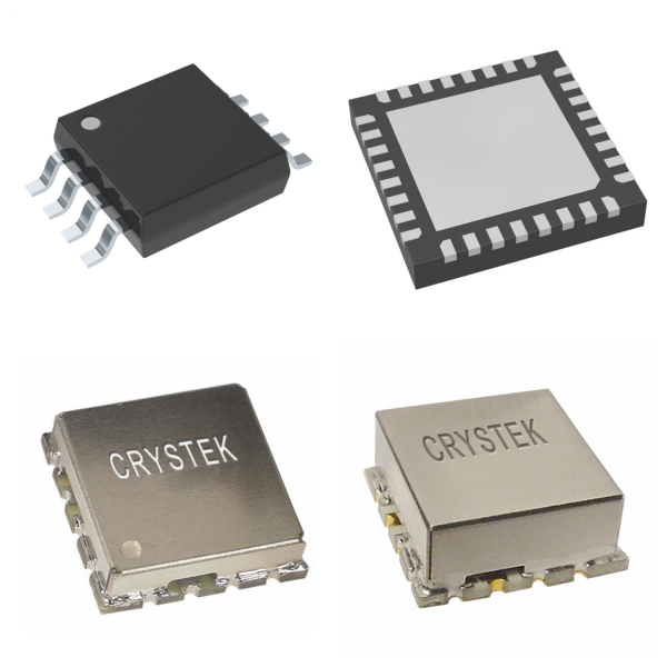
2. What are Oscillators?

Definition: Oscillators are active devices (Active Device), which integrate internal amplifier circuits, feedback resistors and voltage stabilization components, and can independently generate stable frequency signals.

‌Core features‌:

√Directly output clock signals (such as sine waves or square waves) without external driving circuits‌.

√Pins usually include power supply (VCC), ground (GND), output (OUT), etc., and the operating voltage supports 1.8V to 5V‌.

√High frequency stability, less affected by temperature and voltage fluctuations, suitable for high-precision scenarios (such as communication base stations, satellite navigation)‌.

‌Classification‌: Including quartz crystal oscillators (XO), temperature-compensated oscillators (TCXO), voltage-controlled oscillators (VCXO), etc.‌.

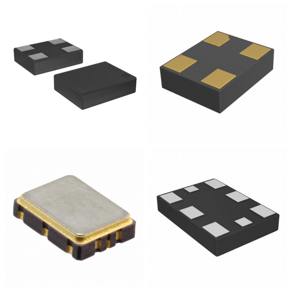
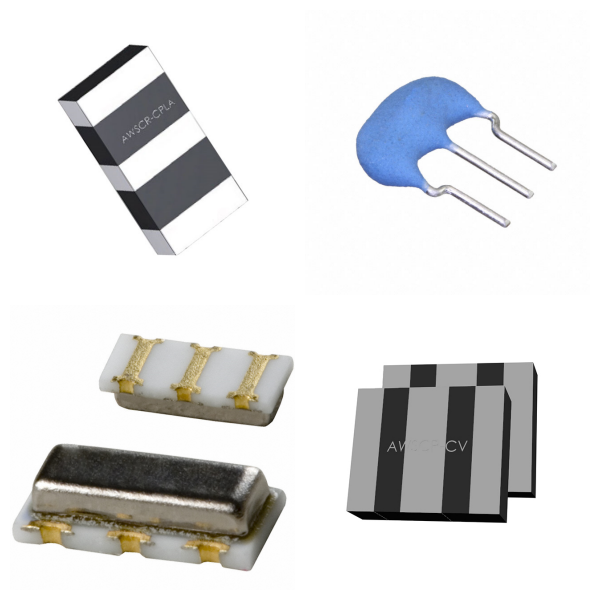
3. What are Resonators? 

‌Definition‌: Resonators broadly include crystal resonators (Crystal Resonators) and ceramic resonators (Ceramic Resonators), both of which are passive devices and require external circuit excitation to work‌.

‌Difference from crystals‌:

√‌Structure‌: Crystal resonators are composed of a single quartz plate; ceramic resonators use piezoelectric ceramic materials, which are lower in cost but lower in precision‌.

√‌Performance‌: Crystal resonators have higher frequency stability and lower aging rates; ceramic resonators are suitable for cost-sensitive medium and low-frequency scenarios (such as home appliance control).

4. Comparison of Crystals, Oscillators and Resonators

‌Features ‌

‌Crystals

‌Oscillators

‌Resonators

‌Device Type

Passive

Active

Passive

‌Drive Requirements

External Circuit Required

No External Circuit Required

External Circuit Required

‌Output Signal

Resonant Signal (Amplification Required)

Direct Output of Stable Clock Signal

Resonant Signal (Amplification Required)

‌Typical Applications

High-precision clock reference

Clock source for complex systems

Low-cost, medium and low-frequency circuits

Cost

Medium

High

Low

5. How to Choose Crystals, Oscillators and Resonators?

‌Accuracy First‌: Select a crystal or oscillator (such as TCXO) and optimize the circuit with load capacitance.

‌Cost Sensitive‌: Ceramic resonators can replace low-frequency crystals, but pay attention to the problem of temperature frequency deviation.

‌Power Consumption Limit‌: Silicon oscillators (such as MAX7375) are better than traditional discrete solutions in low-power scenarios.