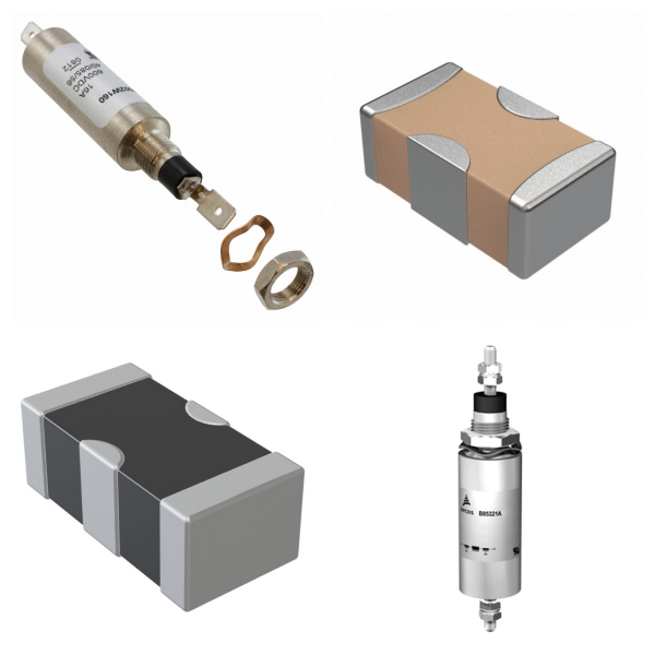
New title

<h1> Cable Ferrites </h1> <p> Ferrite cores are devices that are designed to prevent high frequency noise or EMI (electromagnetic interference). These ferrite cores are made to be placed on cables or wires. Some key characteristics are the type (flat or round), the design (clamp, clip, hinged, solid, or tubular), the inner and outer dimensions, the length, the mounting type (cable tie, chassis mount, or free-hanging), and the impedance at a specific frequency. </p> <p>
<h1> Ceramic Filters </h1> <p> Ceramic filter products provide a frequency dependent characteristic useful for suppressing or selecting signal content over some range of frequencies. Some devices use the piezoelectric properties of a ceramic material to achieve this end and are effectively electro-mechanical systems, whereas others use multi-layer construction techniques, incorporating inductive elements to create an integrated inductor-capacitor (LC) style filter. </p> <p>
<h1> Common Mode Chokes </h1> <p> A common mode choke is an electrical filter that blocks high frequency noise common to two or more data or power lines while allowing the desired DC or low-frequency signal to pass. Common mode (CM) noise current is typically radiated from sources such as unwanted radio signals, unshielded electronics, inverters and motors. Left unfiltered, this noise presents interference problems in electronics and electrical circuits. </p> <p>
<h1> DSL Filters </h1> <p> A DSL filter is an analog low-pass filter installed between analog devices (such as telephones or analog modems) and a plain old telephone service (POTS) line. The DSL filter prevents interference between such devices and a digital subscriber line (DSL) service connected to the same line. Without DSL filters, signals or echoes from analog devices at the top of their frequency range can reduce performance and create connection problems with DSL service, while those from the DSL service at the bottom of its range can cause line noise and other problems for analog devices. </p> <p>
<h1> EMI/RFI Filters (LC, RC Networks) </h1> <p> Products in this family integrate several passive components into a single device in a manner designed to yield a frequency dependent opposition to current flow. Though other types are available, a majority of them are of a low-pass type used to suppress the unwanted transmission of high frequency signals, which might otherwise cause interference or undesired operation. </p> <p>
<h1> Feed Through Capacitors </h1> <p> Feed through capacitors are a variety of devices designed to provide capacitive coupling to a conductor which passes through them. Commonly used for broadband filtering of DC power lines, they are often produced in mechanical form factors designed to be mounted within a conductive enclosure, in context of RF, microwave, and other sensitive applications. </p> <p>
<h1> Ferrite Beads and Chips </h1> <p> Ferrite cores are devices that are designed to prevent high frequency noise or EMI (electromagnetic interference). These ferrite cores are made to be placed within an electric circuit. Key characteristics are the filter type (differential, signal, or power), number of lines, max current rating, impedance and a specified frequency, and mounting type (free hanging, surface mount, or through-hole). </p> <p>
<h1> Ferrite Disks and Plates </h1> <p> Ferrite disks and plates provide a simple and cost-effective solution for radiated and inductively coupled electromagnetic interference. They can be utilized either as inductively coupled components or EMI shields, and can be installed directly on the EMI source. </p> <p>
<h1> Filter Accessories </h1> <p> Supplementary items used with other devices in this category. </p> <p>
<h1> Helical Filters </h1> <p> Helical Filters are designed to remove unwanted frequencies from a circuit. Items in this family use a spirally wrapped wire around a central core. Their center frequencies range from 216 MHz to 1.015 GHz with a bandwidth of 2.6 to 25 MHz, and an insertion loss of 2.5 to 6 dB. </p> <p>
<h1> Monolithic Crystals </h1> <p> Monolithic crystal filter (MCF) products are used in radio and related applications as bandpass filters. Closely related to the quartz crystal resonators used widely for frequency generation, MCF filters employ the piezoelectric and mechanical resonance properties of the quartz material to produce a filter with very high selectivity in a compact package. </p> <p>
<h1> Power Line Filter Modules </h1> <p> Power line filter modules are modularized passive component assemblies that are used to inhibit current flow through power supply conductors at frequencies outside that which is nominal for the intended supply. Commonly used in conjunction with AC utility power sources, they are used both to mitigate interference caused by outside sources as well as suppress potential interference which might be caused by a connected device. </p> <p>
<h1> RF Filters </h1> <p> Radio frequency filter products provide a frequency-dependent level of signal attenuation, and are distinguished from similar products by their intended use in radio-related applications. They are commonly used to limit the amount of interference caused by strong signals outside a frequency range of interest. Component-level products designed to be incorporated into an electronic assembly as well as modular, connectorized products for lab & test equipment use are both included. </p> <p>
<h1> SAW Filters </h1> <p> SAW (Surface Acoustic Wave) Filters are designed to remove unwanted frequencies from a circuit. Items in this family convert signal voltages into acoustic waves at one end of the device. These waves travel the length of quartz device at a specific frequency. The waves are reconverted back to signal voltages on the other end. The bandwidth range is 25kHz to 328MHz with insertion losses of 0.44dB to 23dB. </p> <p>

Filters

Filters can effectively optimize signal integrity and improve the anti-interference ability and performance of electronic systems.

1. Filters Overview

A filter is an electronic circuit or device used for signal processing. Its core function is to improve signal quality by selectively allowing specific frequency components to pass through while suppressing or attenuating other frequency components. Its application scenarios include communication systems, power management, audio processing, and RF front-end.

2. What are the Types of Filters?

1) Classification by frequency characteristics

Low-pass filter (LPF): allows signals below the cutoff frequency to pass through, suppresses high-frequency noise, and is often used for power supply ripple smoothing.

High-pass filter (HPF): allows signals above the cutoff frequency to pass through, and removes low-frequency interference (such as DC offset).

Band-pass filter (BPF): only allows signals in a specific frequency band to pass through, and is used for signal frequency division in communication systems.

Band-stop filter (BSF): suppresses signals in a specific frequency band (such as ground reflection interference in radar systems).

2) Classification by implementation method

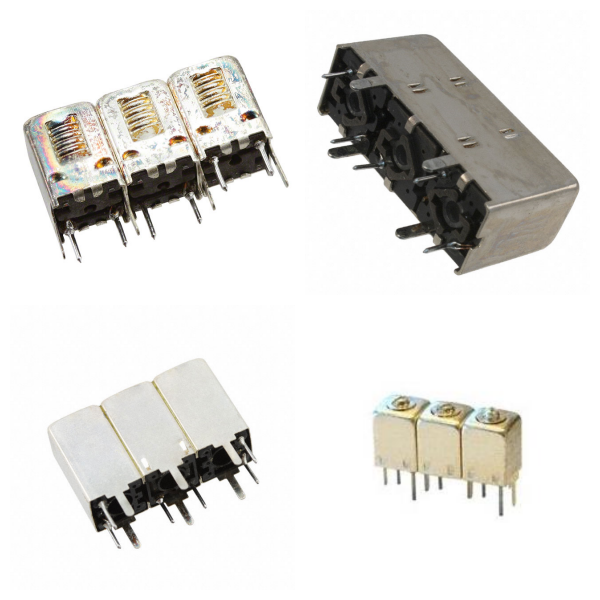
Passive filter: composed of passive components such as resistors, capacitors, and inductors, with low cost, but performance limited by component parameters.

Active filter: combined with active components such as operational amplifiers, with high gain and strong stability.

Digital filter: processes discrete signals through algorithms (such as FIR and IIR filters) with high flexibility.

3) Special Types

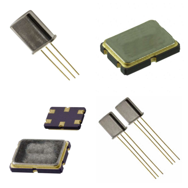
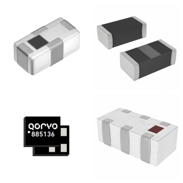
RF filter: used in wireless communication equipment (such as mobile phones and base stations) to solve the problem of interference between frequency bands. Typical types include surface acoustic wave filters (SAW) and bulk acoustic wave filters (BAW).

4. What are the Key Performance Parameters of Filters?

Center frequency: the reference frequency of the filter passband (such as the midpoint frequency of the bandpass filter).

Bandwidth: the frequency range allowed to pass.

Q value (quality factor): the core indicator for measuring frequency selectivity. The higher the Q value, the stronger the frequency selectivity of the filter.

Insertion loss: the power loss when the signal passes through the filter, which needs to be reduced as much as possible.

5. Where are Filters Used for?

1) Communication system

Transmitter: located behind the power amplifier (PA) to filter out harmonic interference.

Receiver: located in front of the low noise amplifier (LNA) to suppress out-of-band noise.
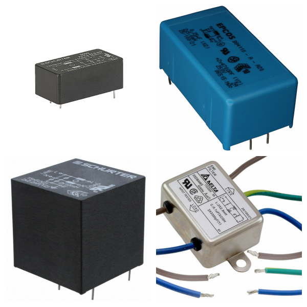
2) Power management

Filter out ripple and noise in the power supply voltage and provide stable DC output.

3) Biomedicine and image processing

A high-pass filter enhances image edge details, and a band-stop filter removes interference in specific frequency bands.

6. How to Choose Filters?

Application scenario requirements: Base station filters require high power capacity and stability, and mobile phone filters require miniaturization and low cost.

Environmental interference type: Select low-pass, high-pass, or band-stop type according to the noise frequency band.

Integration process: SMT (surface mount technology) is suitable for miniaturized RF filter design.

7. Typical Brands for Filters

SCHURTER

MOLEX

TDK

Murata

Xilinx

TI

8. Filters FAQs

1) How do filters work? ‌

Filters achieve their functions through a frequency selection mechanism: they allow signals to pass with minimal attenuation in the passband, while greatly attenuating interference signals in the stopband. For example, a low-pass filter allows low-frequency signals to pass while suppressing high-frequency noise.

2) What is the core difference between digital filters and analog filters? ‌

‌Analog filters‌: They are composed of passive components such as resistors, capacitors, and inductors, and process continuous-time signals. They have a simple structure but low adjustment flexibility.

‌Digital filters‌: They process discrete signals based on algorithms, have strong programmability, and are suitable for high-precision scenarios (such as IIR/FIR filters in communication systems).

‌3) What should be noted when installing filters? ‌

‌Wiring requirements‌: Reserve a "clean ground" at the cable port to avoid direct coupling between the signal ground and the filter ground.

‌Electromagnetic shielding‌: The filter and the chassis must be reliably overlapped, and metal plates or sealing gaskets must be used to reduce RF impedance when necessary.

‌Installation location‌: Keep as close to the interference source or sensitive equipment as possible to shorten the length of the wire after filtering.

‌4) What are the special requirements for RF filters? ‌

‌High-frequency performance‌: Need to support GHz frequency bands, such as SAW/BAW filters commonly used in 5G communications‌.

‌Manufacturing process‌: Use surface acoustic wave (SAW) or bulk acoustic wave (BAW) technology to improve quality factor and temperature stability‌.

5) What are the common causes of filter failure? ‌

‌Environmental factors‌: High temperature causes capacitor capacitance drift, and high humidity causes leakage current or component corrosion‌.

‌Overload damage‌: Exceeding the rated voltage/current causes inductor saturation or capacitor breakdown‌.

‌Design defects‌: Failure to match system impedance causes signal reflection or abnormal insertion loss‌.