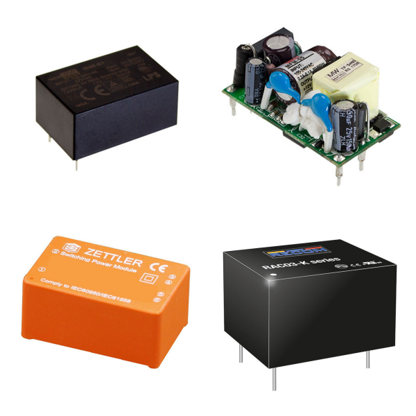
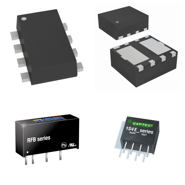
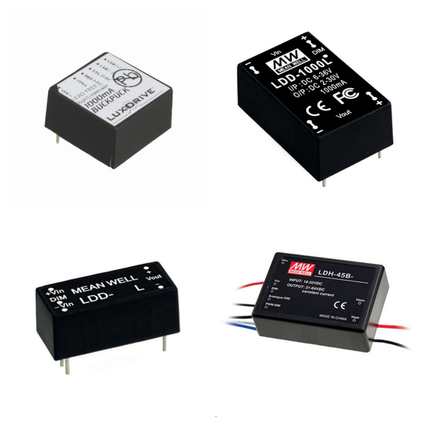
Power Supplies – Board Mount
1. Overview
1)Basic Concepts
“Power Supplies – Board Mount” refers to compact power modules that can be directly mounted on a printed circuit board (PCB), including AC/DC or DC/DC conversion functions, and are used to provide stable power for electronic devices.
2)Main Types
Isolated Modules: The input and output ends are electrically isolated by a transformer, and the isolation voltage is usually 1.5kV-3kV, which is suitable for scenarios with high anti-interference requirements.
Non-isolated Modules: Smaller and lower in cost, suitable for applications with limited space and no isolation.
2. What are the Core Parameters and Features of Board Mounted Power?
1)Input/Output Range
Input Voltage: Covers a wide range of inputs, such as DC 0.7V-15V (low voltage scenario) or AC 90V-264V (universal AC input).
Output Voltage: Supports single or multiple outputs, such as DC 1.8V, 5V, 12V, 500V, etc., to meet different load requirements.
2)Power and Efficiency
The power range is from 4W (AC/DC module) to 120W (high-voltage DC/DC module), and the efficiency is generally higher than 85%, and some models can reach 88.5%.
Adopt interleaved PFC (power factor correction) and PSFB (phase-shifted full-bridge) topology to improve energy efficiency.
3)Safety and Certification
Complies with EN55022 Class B electromagnetic compatibility standard passes 3kV isolation voltage test and has overcurrent (OCP), overvoltage (OVP), and over temperature (OTP) protection functions.
3. What is Board Mounted Power Used for?
Industrial control equipment: such as PLC and sensor power supply, which need to withstand wide temperature environment (-40 °C to 100 °C) and vibration conditions.
Communication infrastructure: CRPS (common redundant power supply) architecture is used in servers and switches to support hot plugging and redundant backup.
Medical and test instruments: Modules that rely on high isolation voltage and low noise output to ensure equipment safety and accuracy.
4. How to Choose Board Mounted Power?
Load matching: Select a model with a power margin of ≥20% based on the device power consumption to avoid overload.
Installation method: Give priority to standard packaging (such as 1/8 Brick size) and compatible with PCB layout requirements.
Management interface: Some modules support PMBus/SMBus protocols to facilitate remote monitoring of power status.
5. Board Mounted Power FAQs
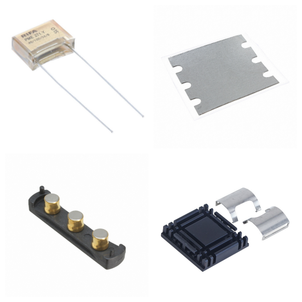
1) Which components are prone to power failure?
Electrolytic Capacitors: Common failures include reduced capacity, leakage, or short circuits, which may cause unstable power output or complete failure.
Resistors: Low-resistance resistors are easily burned due to overcurrent, and high-resistance resistors may drift due to aging, affecting the voltage division or current limiting function of the power supply.
SMT Components: SMT components are small, and poor welding or thermal stress may cause contact failure.
2) How to detect power supply-related component failures?
Capacitor Test: Use a multimeter to measure whether the capacity has decreased, or observe whether there is physical damage such as bulging or leakage.
Resistance Test: Low-resistance resistors are easy to identify when they are burnt and blackened, and high-resistance resistors need to measure whether the resistance is abnormal.
Short Circuit Troubleshooting: Use the adjustable power supply to gradually increase the pressure and observe the heating element to locate the short circuit point.
3) What are the possible reasons for the abnormal output of the power module?
Capacitor Failure: The decrease in the capacity of the filter capacitor will cause the output voltage ripple to increase.
Welding Problem: Cold welding or cold welding may cause poor contact, which may be good or bad.
External Interference: Unshielded power lines may introduce noise, so grounding and shielding measures need to be checked.
4) How to test the stability of power supply output?
Ripple Test: Use an oscilloscope to measure the AC component of the output voltage, which must meet the design specifications (such as <50mV).
Load Regulation: Test the voltage fluctuation range under different loads.
Transient Response: Observe the recovery time and overshoot voltage through step load changes.