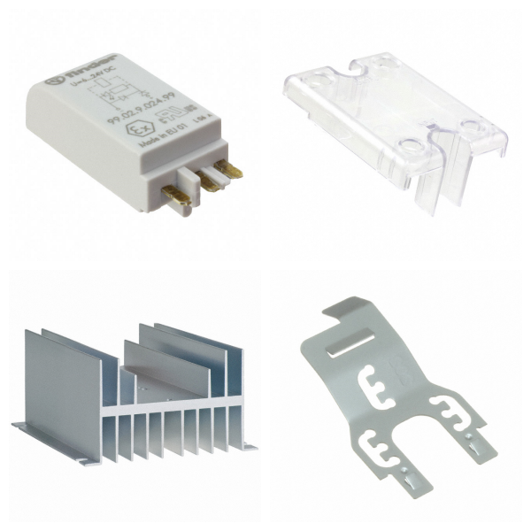

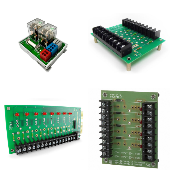
Relays
1. Relays Overview
Relays are electronic switching devices that control the on and off of output circuits through input signals. They can realize the functions of controlling large currents with small currents, isolating strong and weak currents, and switching circuits. Its core functions include automatic adjustment, safety protection, and signal conversion, and are widely used in power systems, automation control, communication equipment, and other fields.
2. How Relays Work?
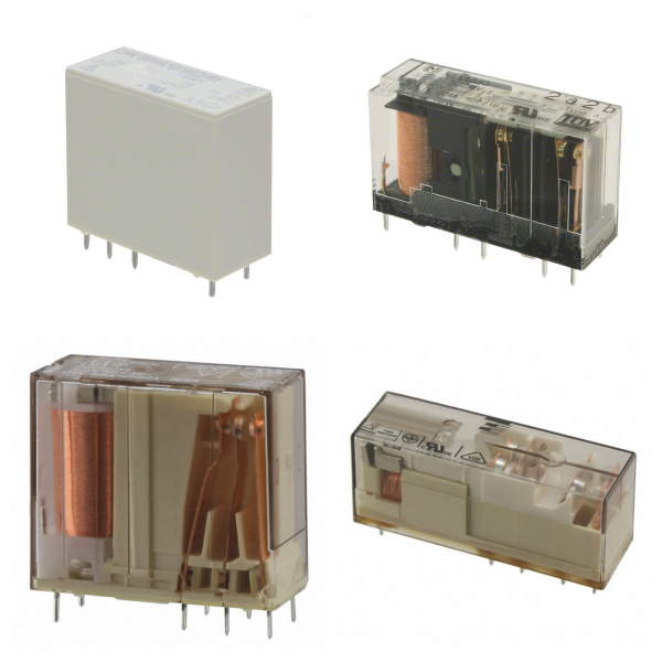
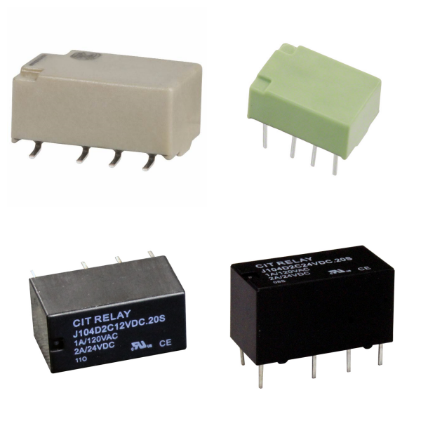
1) Structure Composition
Electromagnetic relay: It is composed of mechanical parts such as an iron core, coil, armature, and contact spring, and relies on electromagnetic effect to drive the contact action.
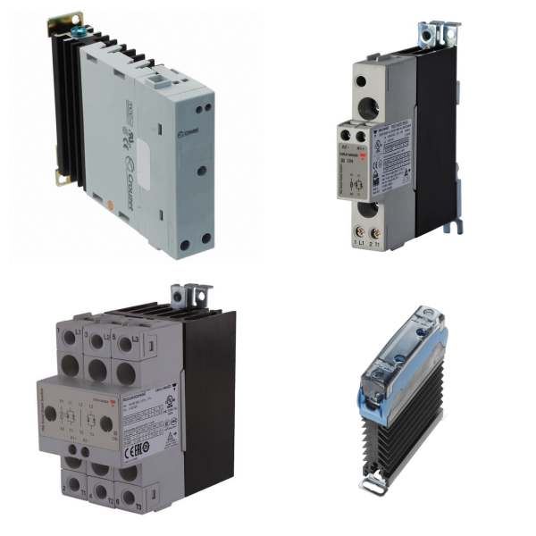
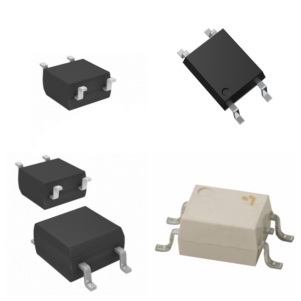
Solid-state relay (SSR): It has no mechanical parts and consists of three parts: input circuit (control signal), drive circuit (photoelectric coupling or high-frequency transformer isolation), and output circuit (semiconductor devices such as thyristor, MOSFET, etc.).
2) Working Principle
Electromagnetic type: When the coil is energized, a magnetic field is generated, which attracts the armature to drive the contacts to close or open, thereby realizing the on and off of the circuit.
Solid-state type: The input control signal is isolated by a photocoupler and then triggers the output semiconductor device to switch the load circuit in a contactless manner.
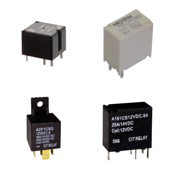
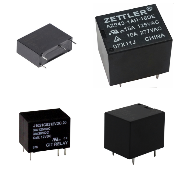
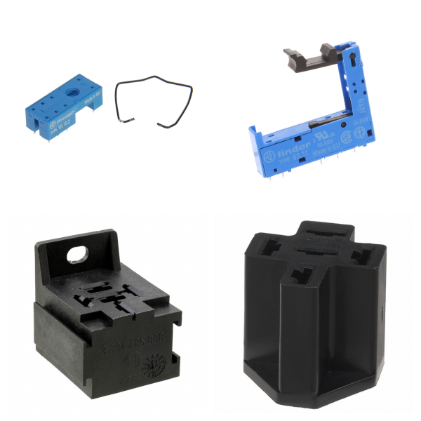
3. What are the Main Types of Relays?
1) Classification by load properties
AC relay: The output end uses a bidirectional thyristor (Triac), which is suitable for AC loads.
DC relay: The output end uses MOSFET or IGBT to control DC loads.
2) Classification by technical characteristics
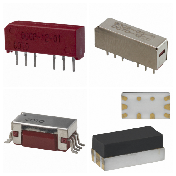
Electromagnetic relay: Low cost, easy wear of contacts, suitable for low-frequency scenarios.
Solid-state relay (SSR): No contacts, long life, fast response, suitable for high-frequency or high-reliability demand scenarios.
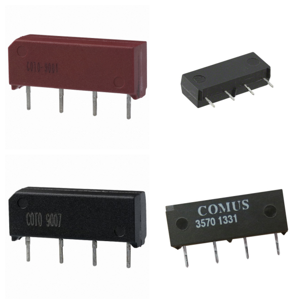
Thermal reed relay: Utilizes the temperature control characteristics of magnetic materials, has a coil-free design, and is suitable for temperature-sensitive scenarios.
4. What are Relays Used for?
Industrial automation: Control high-power equipment such as motors and heaters.
Power system: Realize overload protection, remote control, and signal isolation.
Automotive electronics: used for lighting control, battery management, and other modules.
Smart home: integrated into temperature control and security systems to achieve weak current control of strong current.
5. What are the Differences Between Electromagnetic Relay and SSR?
|
Characteristics |
Electromagnetic relay |
Solid-state relay (SSR) |
|
Contact life |
About 10⁵~10⁶ times (mechanical wear limit) |
10⁷~10⁸ times (contactless design) |
|
Response speed |
Millisecond level (mechanical action delay) |
Microsecond level (semiconductor device response) |
|
Isolation method |
Electromagnetic isolation |
Photoelectric/high-frequency transformer isolation |
|
Anti-interference ability |
Weak (susceptible to arc) |
Strong (no spark interference) |
6. Typical Parameter Examples of Relays
Take model 34.51.7.012.0010 as an example:
√Coil voltage: 12VDC
√Contact capacity: 6A/400VAC (SPDT type)
√Response time: 5ms for pull-in, 3ms for release
√Working temperature: -40 °C ~ 85 °C.
7. How to Choose Relays?
Load Type: Prioritize matching of AC/DC load characteristics.
Environmental Conditions: Solid-state relays are preferred in high-temperature or vibration scenarios.
Life Requirements: Contactless SSRs are required for high-frequency operation.
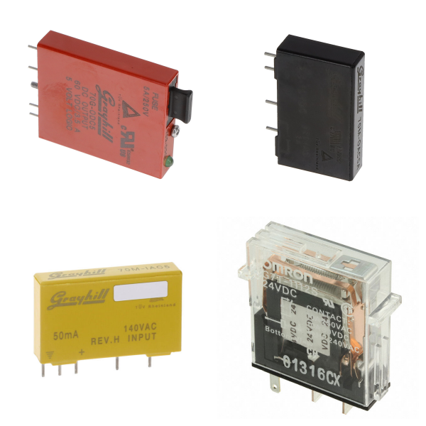
8. Typical Brands for Relays
Panasonic
Omron relay
Schneider
HongFa
SIEMENS
CHNT
9. Relays FAQs
1) What is the Difference between Relay and Contactor?
Relay: Suitable for low power control (usually ≤10A), small size, mostly used in electronic circuits.
Contactor: Designed for high current (tens to hundreds of amperes), commonly used in industrial motor control.
2) What are the Features of the Safety Relay?
Larger in appearance, modular design, mostly red/yellow.
Adopt safety designs such as forced rail contacts to avoid failure caused by contact welding.
3) How to Choose the Coil Voltage?
Need to match the rated voltage range to avoid too high (damage to the coil at high temperature) or too low (cannot work properly). The magnetic latching relay needs to ensure that the excitation pulse width is sufficient to prevent entering the neutral state.
4) How to Suppress the Reverse Peak Voltage When the Coil is Powered Off?
Use transient suppression diodes or resistors, but it will extend the release time; if sensitive to the release time, you can balance it with a series resistor.
5) What is the Effect of Contact Material on the Load?
AgNi+gold Plating: Suitable for small loads (such as signal relays).
AgSnO₂: Suitable for inductive/capacitive loads (inrush current can reach 120A).