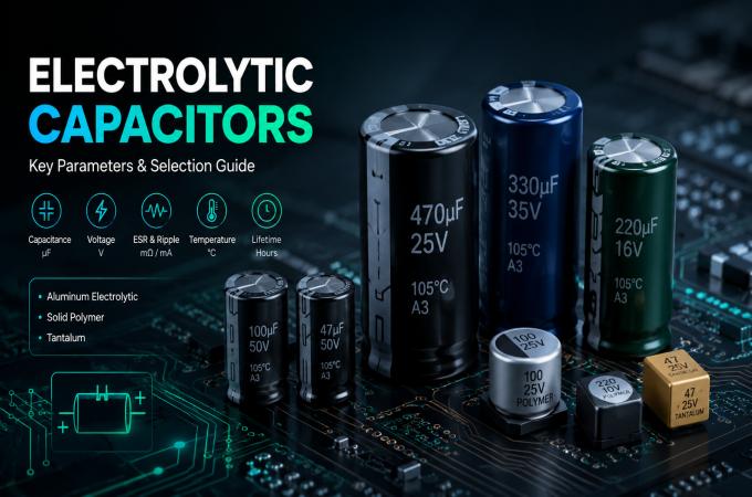
Mastering Electrolytic Capacitor Selection: Your Ultimate Guide
1. Introduction
In the intricate world of electronics, certain components are truly indispensable, and among them, electrolytic capacitors (E-caps) hold a critical position. Known for their ability to pack high capacitance into a relatively small volume, E-caps are the workhorses in countless applications, from robust power systems to crucial low-frequency filtering. However, the sheer variety and specific characteristics of these components mean that choosing the ideal capacitor is far from a trivial task.
For any engineer involved in PCB design, a systematic approach to capacitor selectionis paramount. It extends beyond merely matching a capacitance value; it’s about striking a delicate balance between electrical performance, transient response, and practical considerations like PCB area, cost, and ultimately,component reliability. Missteps in this process can lead to reduced circuit efficiency, shorter product lifespans, and even catastrophic failures.
This comprehensive guide aims to equip you with the knowledge needed to navigate the complexities of selecting electrolytic capacitors. We’ll delve into their fundamental principles, dissect key parameters like ESR and ripple current, explain critical concepts such asvoltage derating, and provide a practical framework to ensure your selections contribute to robust and long-lasting designs. Let’s move from theoretical understanding to confidentbill of materials (BOM) preparation.
2. Understanding Electrolytic Capacitors
At their core, electrolytic capacitors are specialized types of polarized capacitors, meaning they must be installed with correct polarity relative to the DC voltage in a circuit design. Their operational mechanism relies on a very thin dielectric layer formed through an electrolytic oxidation process. This thin dielectric is key to achieving high capacitancevalues in a compact form factor.
Types of Electrolytic Capacitors
The world of electrolytic capacitors is diverse, primarily categorized by their anode material and electrolyte type. The two major families are aluminum electrolytic capacitors and tantalum capacitors, each with unique characteristics and typical applications.
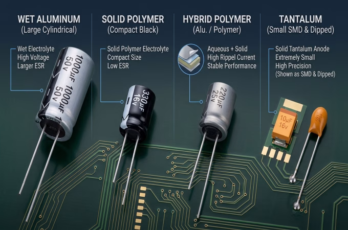
- Aluminum Electrolytic Capacitors: These are the most common type and come in several variants:
- Wet (Liquid) Electrolyte: The most traditional and widely used. They offer high capacitance, are cost-effective, and tolerate high ripple currents. However, they are susceptible to drying out over time, especially at elevated temperatures, leading to degradation.
- Solid Polymer Electrolyte: Utilizing a solid conductive polymer instead of a liquid, these capacitors boast significantly lower ESR, better stability over temperature, and a longer lifespan. They are often found in high-frequency applications like DC-DC converters.
- Hybrid Polymer Electrolyte: Combining the benefits of both wet and solid types, these offer lower ESR and higher ripple current ratings than wet types, while also being more robust than solid polymers in certain conditions.
- Tantalum Capacitors: Known for their excellent volumetric efficiency (high capacitance in a small size), high stability, and low ESR. They are typically used in smaller, more critical applications. However, they are generally more expensive and have specific failure modes if over-voltage or reverse-voltage conditions occur.
Electrolytic capacitors also come in various physical forms, often dictated by their intended application and mounting requirements on the PCB. Common form factors include radial, axial, snap-in, and computer-grade types. Radial leaded capacitors are prevalent for general-purpose board mounting, while snap-in versions are typical for larger, higher-voltage applications in power supplies.
To help illustrate the differences, here’s a brief comparison:
| Type | Key Advantages | Key Disadvantages | Typical Applications |
| Wet Aluminum Electrolytic | High capacitance , low cost, high ripple current tolerance |
Limited lifespan (drying out), higher ESR than polymers, temperature sensitive | Power supplies, audio coupling, general filtering |
| Solid Polymer Aluminum | Very low ESR, long life, stable over temperature |
Higher cost, less robust to voltage spikes than wet, specific failure modes | DC-DC converters, CPU voltage regulators, high-frequency filtering |
| Hybrid Polymer Aluminum | Good balance of ESR, lifetime, ripple current, and cost |
Intermediate cost, specific failure modes | Automotive electronics, industrial power supplies |
| Tantalum Electrolytic | High volumetric efficiency, high stability, low ESR | Higher cost, sensitive to over-voltage/reverse-voltage, specific failure modes | Medical devices, portable electronics, signal coupling |
3. Key Parameters for Optimal Electrolytic Capacitor Selection
Beyond the basic capacitance value, a host of other parameters critically influence the performance, reliability, and lifespan of an electrolytic capacitor in your PCB design. Overlooking any of these can lead to compromised component reliabilityand system failure.
Capacitance (C)
This is the most fundamental parameter, determining the capacitor’s ability to store electrical charge. The required capacitance depends entirely on the application: filtering, smoothing, timing, or energy storage. For instance, in power supply output filtering, higher capacitance helps reduce voltage ripple. However, simply choosing the largest capacitance isn’t always best; it can increase size, cost, and inrush current.
Rated Voltage (WVDC)
The maximum DC voltage that can be continuously applied to the capacitor without damage. Crucially, a capacitor should never be operated at its exact rated voltage.Voltage deratingis a critical design practice, typically recommending that the operating voltage be 70-80% of the rated voltage (e.g., for a 10V operating voltage, a 16V or 25V capacitor might be elected). This derating provides a safety margin against voltage spikes, temperature variations, and extends the capacitor’s lifespan. Ignoring this can lead to dielectric breakdown and catastrophic failure, especially for tantalum capacitors.Proper voltage derating is key forlong-term product reliability.
Equivalent Series Resistance (ESR)
ESR represents the sum of all resistive losses within the capacitor, including lead resistance, electrode resistance, and electrolyte resistance. LowESRis vital for applications requiring efficient filtering, fast transient response, and minimal power dissipation. High ESR can lead to:
- Increased voltage ripple, especially in switch-mode power supplies.
- Higher internal heating, reducing the capacitor’s lifespan.
- Reduced efficiency of the power conversion stage.
Solid polymer and hybrid polymer capacitors typically offer significantly lower ESR compared to wet aluminum electrolytics, making them ideal for high-frequencypower systems.
Ripple Current Rating
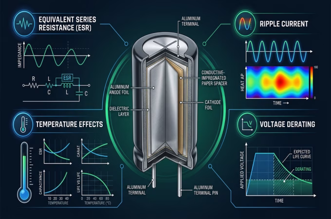
The maximum RMS value of AC current that can flow through the capacitor without causing excessive internal heating. When ripple current flows through the capacitor’sESR, it generates heat (P = I²R). Exceeding the rated ripple current will cause the capacitor’s internal temperature to rise beyond its specified limit, accelerating electrolyte evaporation (in wet types) and drastically shortening its operational life. Designers must carefully calculate the expectedripple currentin their application and select a capacitor
with a sufficiently high rating, often with a safety margin.
Operating Temperature Range
Capacitors are specified for a particular operating temperature range (e.g., -40°C to +
85°C or +105°C). Performance characteristics likecapacitance,ESR, and leakage current can vary significantly with temperature. Operating a capacitor above its maximum rated temperature will drastically reduce its lifespan. Conversely, operating below the minimum temperature can lead to increased ESR and reduced capacitance, impairing circuit performance.
Lifetime / Endurance
Often specified in hours at a given temperature (e.g., 2,000 hours at 105°C), this indicates the expected operational life of the capacitor. Elevated temperatures and highripple currentare the primary factors that degrade a capacitor’s lifespan. For every 10°C reduction in operating temperature, the lifespan of electrolytic capacitors (especially wet types) can roughly double (Arrhenius equation approximation). Selecting a capacitor with a higher temperature rating or operating it below its maximum can significantly extend its useful life, contributing directly tolong-term product reliability.
Tolerance
Indicates the permissible deviation from the nominal capacitance value (e.g., ±20%). Electrolytic capacitors typically have wider tolerances compared to ceramic or film capacitors. For filtering applications, a wider tolerance is often acceptable, but for timing or precision circuits, a tighter tolerance might be necessary, though it usually comes at a higher cost.
Package Size and Form Factor
The physical dimensions (diameter, height, lead spacing) and mounting style (radial, axial, snap-in, surface mount) are crucial for PCB design. Space constraints on a board can dictate the maximum allowable size, potentially influencing the choice between different capacitor types or even vendors.Considering package sizeearly in the design phase prevents costly redesigns.
Cost
While technical specifications are paramount, cost remains a practical consideration, especially in high-volume production. Balancing performance requirements with budget constraints is a key aspect of capacitor selection. Sometimes, a slightly higher-spe capacitor
might be more expensive upfront but can save costs in the long run by improving component reliabilityand reducing warranty claims.
4. A Step-by-Step Selection Guide for PCB Design
Selecting the right electrolytic capacitor requires a methodical approach. Follow these steps to ensure you make informed decisions for your PCB design, moving effectively from design theory to bill of materials (BOM)preparation.
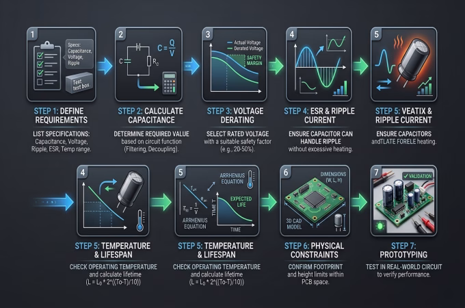
Step 1: Define Application Requirements
Before anything else, clearly understand what the capacitor needs to do.
- Function:Is it for input filtering, output smoothing, coupling, energy storage, or bulk capacitance?
- Operating Voltage:What is the maximum continuous DC voltage and potential peak voltages?
- Operating Current:What is the expected AC ripple current and DC load current?
- Operating Frequency:What are the dominant frequencies in the circuit? This impacts ESR requirements.
- Environmental Conditions:What are the expected ambient temperature range and any specifichumidity or vibration requirements?
- Desired Lifespan:What is the target operational life for the end product?
Step 2: Calculate Required Capacitance
Based on the application, determine the nominalcapacitancevalue. For example, in a power supply output filter, the capacitance is often calculated based on the allowable ripple voltage, switching frequency, and load current. Use appropriate formulas for your specificcircuit design.
Step 3: Apply Voltage Derating
This is a critical safety and reliability step. Always select a capacitor with a rated voltage significantly higher than the maximum operating voltage. A common practice is to use a derating factor of 0.7 to 0.8. So, if your maximum operating voltage is 10V, choose a capacitor rated for 16V (10V / 0.7 = ~14.3V) or even 25V for extra margin. This is especially vital forlong-term product reliability.
Step 4: Consider ESR and Ripple Current
Evaluate the anticipatedripple current(RMS) that will flow through the capacitor. Select a capacitor with aripple currentrating that exceeds your calculated value, typically with a safety margin (e.g., 20-30%). Simultaneously, consider the required ESR for your application. For power systems, lower ESR is generally better to minimize heating and ripple.
Step 5: Account for Temperature and Lifespan
Ensure the capacitor’s operating temperature range covers your application’s environmental conditions. Then, verify the capacitor’s specified lifespan at its rated temperature. If your operating temperature is lower, you can typically expect a longer lifespan (using the 10°C rule of thumb). For demanding applications, prioritize capacitors with higher temperature ratings (e.g., 105°C instead of 85°C) or longer specified endurance.
Step 6: Evaluate Physical Constraints and Cost
Check the capacitor’s physical dimensions against the available space on your PCB. Consider the form factor (radial, axial, SMD) that best suits your manufacturing process and board layout. Finally, compare the cost of suitable components from various manufacturers, ensuring that cost reduction does not compromise critical performance orcomponent reliability. This helps streamline yourbill of materials (BOM).
Step 7: Prototyping and Testing
Always validate your capacitor selection in a prototype. Measure actual ripple voltage, temperature rise across the capacitor, and overall circuit performance. This empirical testing can catch issues that might not be apparent from datasheet analysis alone, solidifying yourcapacitor selection.
Ready to source high-quality electrolytic capacitors?Explore our wide range of aluminum, polymer, and tantalum electrolytic capacitors with detailed specifications and competitive pricing.
5. Common Mistakes to Avoid in Capacitor Selection
Even experienced engineers can fall prey to common pitfalls when selecting electrolytic capacitors. Avoiding these mistakes is crucial for ensuringcomponent reliabilityand the long-term success of your product.
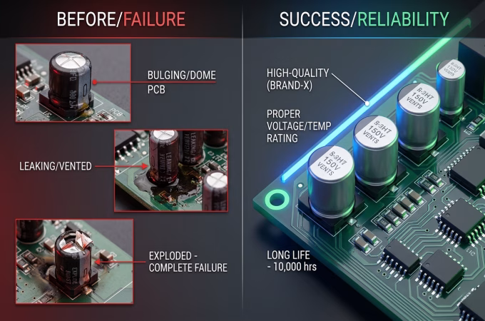
- Ignoring Voltage Derating:Operating a capacitor too close to its rated voltage is perhaps the most frequent and costly mistake. It drastically reduces lifespan, increases failure rates, and can lead to dielectric breakdown. Always apply a generousvoltage d
- Underestimating Ripple Current:Failing to correctly calculate or account for the peakripple currentcan cause severe internal heating, leading to premature capacitor failure, especially inpower systems. Always choose a capacitor with aripple currentrating sufficient for your application, considering temperature multipliers.
- Overlooking ESR:While not always critical for simple DC smoothing, in high-frequency applications like switch-mode power supplies, a highESR can lead to excessive heat, poor regulation, and inefficient operation. Ensure the ESR is low enough for your operating frequency.
- Misjudging Operating Temperature:Capacitors are sensitive to heat.Placing
them near hot components or failing to account for ambient temperature and self-heating due toripple currentcan significantly shorten their lifespan. Always factor in worst-case thermal conditions. - Choosing Based Solely on Capacitance or Cost:Whilecapacitance is fundamental, it’s just one piece of the puzzle. Similarly, opting for the cheapest component without considering all other parameters is a recipe for disaster. A balance of performance, reliability, and cost is essential for effectivecapacitor selection.
- Incorrect Polarity:Electrolytic capacitors are polarized. Reversing the polarity can lead to rapid degradation, venting, and even explosion, especially with wet aluminum types. Always double-check polarity markings duringPCB designand assembly.
- Ignoring Shelf Life and Reforming:Some electrolytic capacitors, especially older wet types, can require “reforming” if stored for extended periods without power. This process re-establishes the dielectric layer. Ignoring this can lead to high leakage currents on initial power-up.
Want to avoid the complexities of capacitor selection? Our technical team possesses extensive experience and can assist you by reviewing your design or recommending suitable products. Please feel free to contact us at any time for professional support.
6. FAQ
- Question1:What is the main difference between aluminum and tantalum electrolytic capacitors?
Answer: Aluminum electrolytic capacitors are generally larger, less expensive, and tolerant of higher ripple currents, making them common in power systems and general filtering. Tantalum capacitors offer higher volumetric efficiency (smaller size for the same capacitance), lower ESR, and better temperature stability, but are more expensive and sensitive to over-voltage and reverse-voltage conditions. - Question2:Why is voltage derating so important for electrolytic capacitors?
Answer : Voltage derating is crucial because operating a capacitor at or near its maximum rated voltage significantly stresses the dielectric, accelerating degradation and leading to premature failure. Derating (e.g., using 70-80% of the rated voltage) provides a safety margin against voltage spikes and temperature variations, dramatically extending the capacitor’s lifespan and improving component reliability. - Question3:How does ESR affect an electrolytic capacitor’s performance?
Answer: ESR (Equivalent Series Resistance) is a critical parameter, especially in high- frequency applications. High ESR leads to increased power dissipation (heat generation) when ripple current flows through the capacitor (P = I² R). This heat reduces the capacitor’s lifespan and can cause increased ripple voltage in filters and reduced efficiency in power converters. Low ESR capacitors are essential for optimal performance in many modern circuit design applications.
7. Summary
Mastering electrolytic capacitor selectionis a vital skill for any electronics engineer, directly impacting the performance, efficiency, and long-term product reliability of a design. We’ve explored the diverse types of E-caps and delved into the critical parameters—capacitance,voltage derating,ESR,ripple current, temperature, and lifespan—that must be carefully considered. By following a structured selection process and actively avoiding common mistakes, you can move confidently from initial concept to a robustbill of materials (BOM). Remember, the right capacitor isn’t just about the numbers; it’s about fitting the component precisely to the demands of your PCB designand ensuring the longevity of your power systems. Prioritizing quality and diligent analysis over mere cost will always pay dividends in reliable electronic products.
8. Key Takeaways
- Derate Voltage:Always apply a significantvoltage deratingmargin (e.g., 70-80%) to maximize capacitor lifespan and prevent failures.
- Mind the Ripple:Calculate and ensure your capacitor’sripple currentrating exceeds the application’s demands to prevent overheating and premature degradation.
- ESR is Critical:For high-frequencypower systems and efficient filtering, prioritize capacitors with low ESR to minimize power loss and ripple.
- Temperature Matters:Operating temperature is a major factor in capacitor lifespan; select components rated for your environment and account for self-heating.
- Holistic Selection:Don’t choose solely based oncapacitanceor cost. A systematic approach considering all key parameters is essential forcomponent reliabilityand successful PCB design.
As part of the same trusted team,we are excited to introduce our brand: OrinewPCB for faster,high-quality One-Stop PCB assembly services.

