Open vs Closed Circuit: Design, Diagnostics, & Safety Guide
1. Introduction
Imagine flicking a light switch, only for the room to remain dark. Or perhaps you’re working on an electronic device, and despite everything seeming connected, it simply won’t power on. In many such scenarios, the root cause lies in understanding a fundamental concept of electricity: the difference between an open circuit and a closed circuit. These two states are not merely academic distinctions; they are the bedrock of electrical safety, efficient troubleshooting, and robust circuit design.
For anyone involved with electronics – from hobbyists building simple gadgets to engineers designing complex systems – grasping the nuances of open vs closed circuit is paramount. An unintended open circuit can lead to wasted diagnostic hours, while an unintended closed circuit might waste power or even create hazardous conditions. This comprehensive guide will demystify these concepts , providing you with the knowledge to design, diagnose, and handle electrical systems with confidence and expertise.
Key Takeaways
- Open Circuit = No Current:A break in the path means electrons cannot flow, preventing loads from operating.
- Closed Circuit = Current Flow:A complete path allows electrons to flow, enabling devices to function.
- Voltage Can Still Be Present in Open Circuits:Always assume a circuit is live until you’ve verified zero voltage.
- Resistance is Key:Open circuits have infinite resistance at the break; closed circuits have finite resistance that dictates current.
- Critical for Safety & Design:Understanding these states is vital for avoiding hazards, accurate diagnostics, and effective circuit design.
- Multimeters are Your Friend:Use continuity and voltage tests to identify and troubleshoot circuit states.
2. What is an Electrical Circuit?
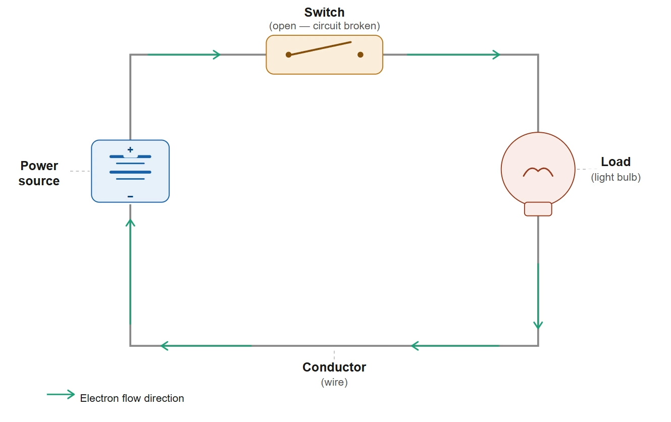
Before diving into open and closed states, let’s establish a clear understanding of what an electrical circuit truly is. At its core, an electrical circuit is a complete, closed loop or path through which electric current can flow. It’s the building block of every electronic device, from a simple flashlight to complex computers and smartphones. Essential components of a basic circuit typically include:
- Power Source:A device that provides the energy to drive the current, such as a battery or a generator. This creates a voltage difference.
- Conductors:Wires or other conductive materials (e.g., copper traces on a PCB ) that provide the path for electrons to flow.
- Load:A component that consumes electrical energy and converts it into another form (e.g., light, heat, motion). Examples include light bulbs, resistors, motors, or LEDs.
- Switch (Optional but common):A device used to control the flow of current by either breaking or completing the circuit.
The movement of electrons from the higher potential of the power source, through the conductors and the load, and back to the lower potential of the source constitutes the current flow.
3. Understanding the Open Circuit
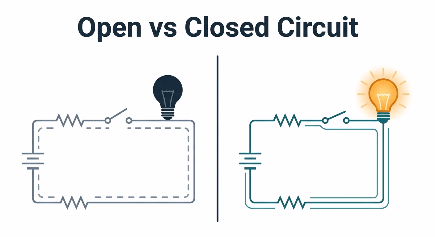
An open circuit is exactly what its name suggests: a circuit that is broken or “open.” This means there is an interruption in the continuous path that prevents electric current from flowing. Think of it like a bridge that has a section missing – nothing can cross from one side to the other.
Characteristics of an Open Circuit:
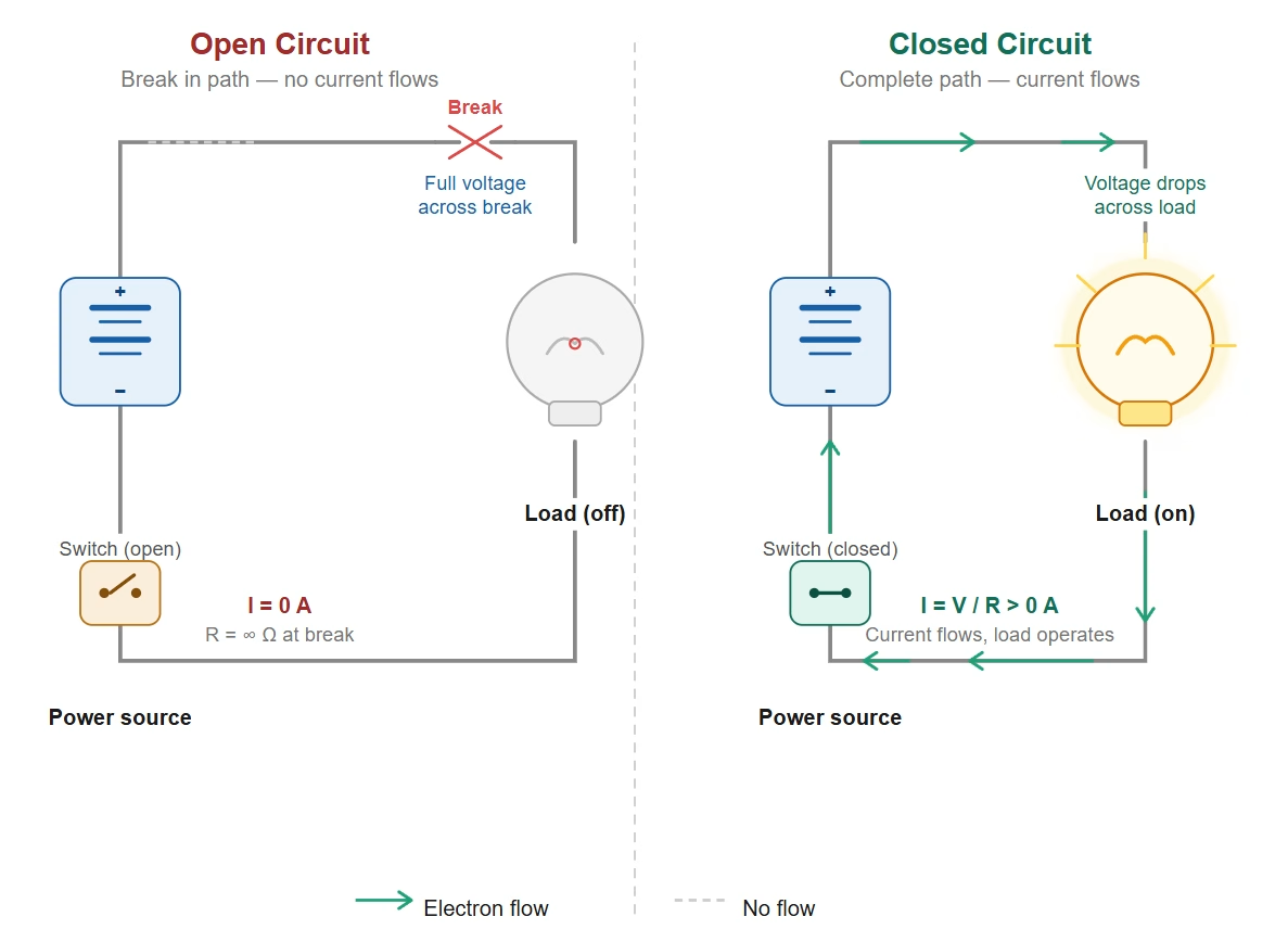
- No Current Flow:The defining feature of an open circuit is that virtually no current (I ≈ 0 Amps) can flow through the break. Even if a voltage source is present, the path is incomplete.
- Voltage Presence:While current cannot flow through the break, voltage may still be present across the break. For instance, if you measure across the open switch in a circuit connected to a battery, you would read the battery’s full voltage.
- Infinite Resistance:Theoretically, the resistance of an open circuit at the point of the break is considered infinite, as there’s no continuous conductive path for electrons.
- Load Inactivity:Any load (like a light bulb or motor) in an open circuit will not operate because there is no current to power it.
Common Causes and Examples:
Open circuits can occur intentionally or unintentionally. An intentional open circuit is created by opening a switch to turn off a device. Unintentional open circuits, which often cause diagnostic headaches, can result from:
- Broken Wire:A physically severed wire or a loose connection.
- Blown Fuse:A safety device designed to create an open circuit when current exceeds a safe limit.
- Dam aged Component:A component with an internal break, like a burnt-out filament in a light bulb or a fractured trace on a PCB.
- Loose Terminal:A wire not properly secured to a terminal or connector .
Recognizing an open circuit is the first step in troubleshooting many electrical issues. If a device isn’t working and voltage is present but current isn’t flowing, an open circuit is the likely culprit.
4. Unveiling the Closed Circuit
In contrast to an open circuit, a closed circuit provides a complete, uninterrupted path for electric current to flow from the power source, through all components, and back to the source. This is the operational state for virtually all electrical and electronic devices.
Characteristics of a Closed Circuit:
- Current Flow:The defining characteristic is the continuous flow of current (I > 0 Amps) throughout the entire loop. Electrons move freely, carrying energy.
- Voltage Drop Across Load:While voltage is present from the source, it drops across the load component selections as energy is consumed. The voltage across the entire closed loop (excluding the source) will be essentially zero if there are no open paths or significant resistance outside the load.
- Finite Resistance:A closed circuit has a measurable, finite resistance, determined by the components within the circuit (e.g., resistors, the internal resistance of a light bulb). This resistance dictates the amount of current flow according to Ohm’s Law (V=IR).
- Load Operation:Loads in a closed circuit perform their intended work. A light bulb illuminates, a motor spins, or an LED lights up.
Common Examples:
- Flashlight On:When you switch on a flashlight, you complete a circuit, allowing current to flow from the batteries, through the bulb’s filament, and back.
- Computer Operating:Inside your computer, countless closed circuits allow processors, memory, and other components to function.
- Household Appliances:From refrigerators to washing machines, all operate when their internal circuits are closed and power is supplied.
While generally desirable, not all closed circuits are good. A “short circuit” is an unintended closed circuit where current bypasses the intended load through a path of very low resistance. This can lead to excessive current flow, overheating, component damage, and potential fire hazards, highlighting the importance of proper circuit design and protection mechanisms.
5. Open vs. Closed Circuit: A Comparative Analysis
To solidify your understanding, here’s a direct comparison of the key differences between open and closed circuits:
| Feature | Open Circuit | Closed Circuit |
| Definition | A circuit with a break in the conductive path, preventing current flow. | A complete and continuous conductive path, allowing current flow. |
| Current Flow | Zero (or negligible) current (I ≈ 0 A). | Current flows through the entire path (I > 0 A). |
| Voltage | Full source voltage appears across the break; zero voltage across the rest of the circuit (if no other loads). | Voltage drops across the load components as energy is consumed. |
| Resistance | The oretically infinite at the point of the break. | Finite and measurable, determined by the components in the circuit. |
| Load Status | Load does not operate; no work is done. | Load operates; performs its intended function. |
| Purpose | Used to switch off devices; often an unintended fault. | The operational state for electrical devices. |
| Safety Implications | Generally safe, but can lead to frustration during troubleshooting . | Can be hazardous if a short circuit occurs, leading to overheating or fires. Requires careful electrical safety measures. |
6. Why This Distinction Matters : Design, Diagnostics, & Safety
Understanding the difference between open and closed circuits isn’t just theoretical; it has profound practical implications across various aspects of electrical engineering and everyday life.
Circuit Design and Component Selection
When designing any electrical system, engineers meticulously plan for both open and closed states. Switches are placed strategically to intentionally open and close circuits, controlling power to different component selections. Circuit design must ensure that all connections are robust to prevent unintentional open circuits and that protective devices like fuses and circuit breakers are included to safeguard against dangerous short circuits (a type of unintended closed circuit).
The choice of component selection also hinges on these concepts. Resistors, for example, are chosen to manage current flow in a closed circuit, while the voltage ratings of components consider the potential voltage presence even in an open circuit scenario.
Efficient Troubleshooting
For electricians and technicians, the ability to quickly differentiate between an open and closed circuit is crucial for fast troubleshooting. If a device isn’t working:
- No Power at the Source:This isn’t an open circuit; it’s a lack of power.
- Power at Source, No Power at Load:This points strongly to an open circuit somewhere between the source and the load. Common tools like multimeters are used to check for voltage (to confirm power supply) and continuity (to identify breaks).
- Device Overheating/Smoking:This indicates an unintended closed circuit (short circuit) allowing excessive current.
By systematically checking for continuity and voltage, one can quickly pinpoint whether a problem is due to a broken wire (open circuit), a faulty switch (open circuit), or an overload (potential short circuit). This saves diagnostic hours and reduces repair time.
Enhanced Electrical Safety
Electrical safety is perhaps the most critical reason to understand these concepts. Working on live circuits, especially those that are closed, carries significant risk of electric shock. Knowing when a circuit is truly open (and thus safe to work on) versus when it’s still carrying voltage (even if no current flows through a specific break) is vital. For example, simply turning off a light switch creates an open circuit for the bulb, but the wiring leading to the switch may still be part of a closed circuit elsewhere in the house, carrying dangerous voltage.
Furthermore, preventing unintended short circuits is a cornerstone of electrical safety. Proper insulation, grounding, and the use of protective devices are all designed to manage current flow and prevent hazards when circuits are closed.
7. Practical DIY Tests & Troubleshooting
For DIY enthusiasts and basic troubleshooting , a multimeter is an invaluable tool. Here’s how you can use it to identify open vs. closed circuits:
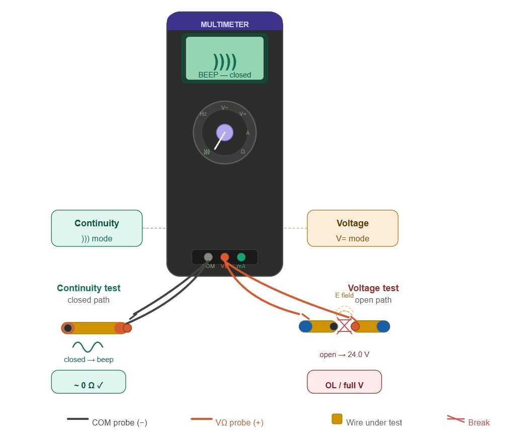
Continuity Test (for Open Circuits):
A continuity test checks if there’s a complete path for current to flow. It’s ideal for finding breaks in wires, fuses, or component paths.
- Safety First:Always disconnect power from the circuit you’re testing. An unintentional closed circuit can be dangerous.
- Set Multimeter:Turn your multimeter to the continuity setting (often indicated by a speaker icon or ohms symbol).
- Test Leads:Touch the multimeter’s probes together. You should hear a beep (indicating continuity) or see a reading close to 0 ohms.
- Test Component: Place one probe at one end of the wire or component and the other probe at the other end.
- Interpret Results:
- Beep/Low Resistance (e.g., & lt; 5-10 Ohms):Indicates a continuous, closed path. The circuit or component is likely intact.
- No Beep/Open Line (OL) Reading/Infinite Resistance:Indicates an open circuit . There’s a break in the path, preventing current flow.
Voltage Test (for Closed Circuits & Voltage Presence):
A voltage test helps determine if power is present and where it drops across component selections in a closed circuit, or across the break in an open one .
- Safety First:Ensure the circuit is powered on if you’re checking for live voltage. Exercise extreme caution.
- Set Multimeter:Set your multimeter to the appropriate AC or DC voltage range (e.g., 20V DC for battery circuits, 200V AC for wall outlets).
- Test Points:
- Across a Power Source:Place probes across the terminals of a battery or power source to confirm it’s supplying voltage.
- Across a Load (Closed Circuit):In a functioning closed circuit, you’ll see a voltage drop across the load (e.g ., a light bulb) as it consumes power.
- Across a Break (Open Circuit):If there’s an open circuit (e.g., an open switch or a broken wire) with power applied to the circuit, you ‘ll measure the full source voltage across that break. This confirms that power is getting to the break, but not past it.
- Interpret Results:
- Reading matches source voltage (across a break):Indicates an open circuit at that point.
- Significant voltage drop (across a load):Indicates the load is functioning in a closed circuit.
- Zero voltage:Could mean no power to the circuit, or you’re measuring across a continuous path in a closed circuit (e.g., across a simple wire with no load).
8. Quantitative Analysis: Current, Voltage, and Power
Moving beyond qualitative descriptions, engineers rely on precise numerical relationships to characterize circuit states. Ohm’s Law and the power equation provide the foundation for translating open or closed circuit conditions into real engineering values — numbers that govern component sizing, fuse selection, and energy budgeting.
Current (I) in Each State
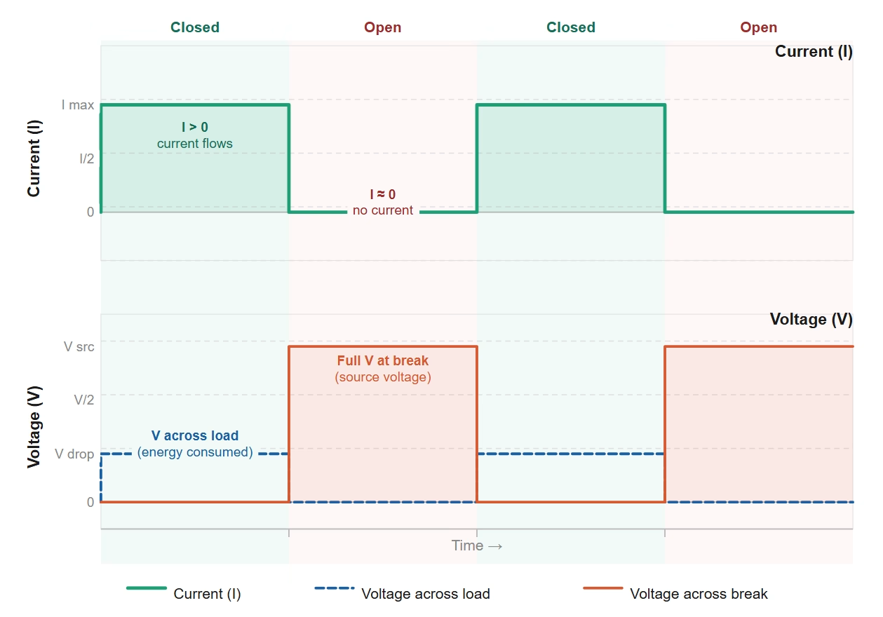
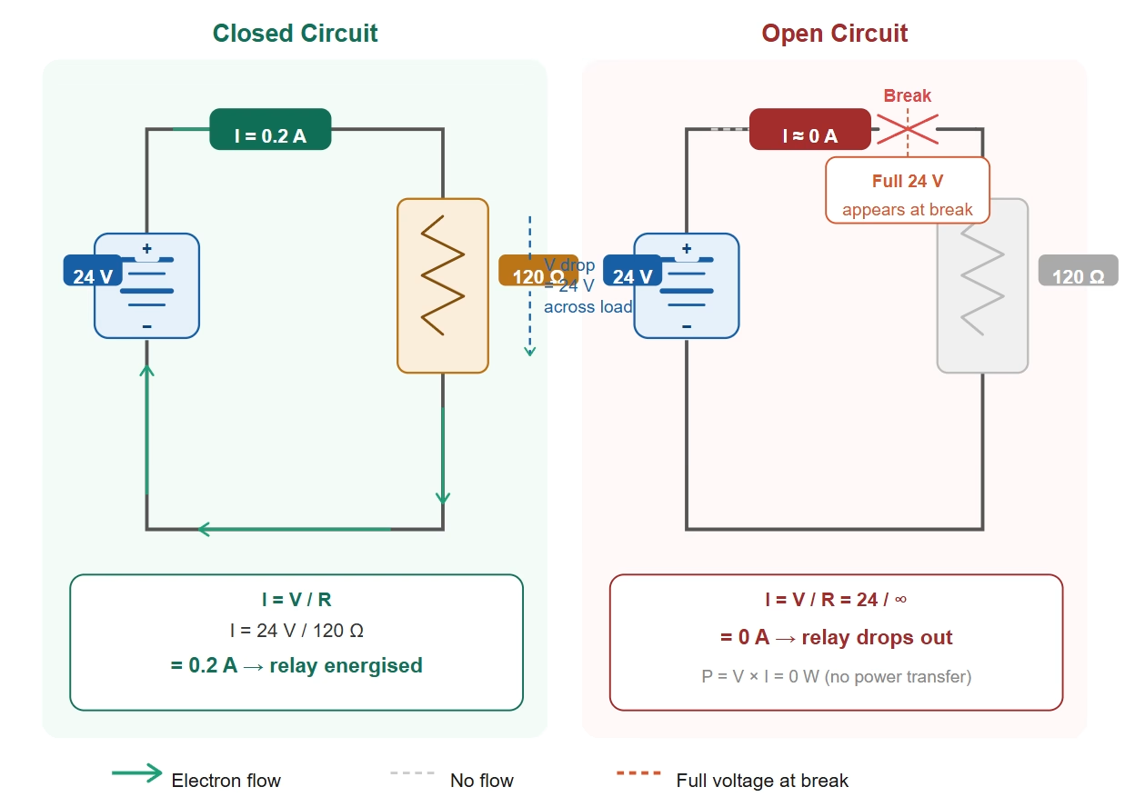
In a closed circuit, current is determined by the supply voltage divided by the total resistance (I = V / R). For example, a 24 V supply driving a load with 120 Ω of resistance produces I = 24 / 120 = 0.2 A (200 mA). This figure determines whether a relay energises, a motor spins, or an LED reaches its rated brightness.
The moment the path is broken — a switch opens, a fuse blows, or a wire fractures — the circuit transitions to the open state and current drops to I ≈ 0 A regardless of how much voltage the source can provide. This hard-zero characteristic is what makes the open state a clean diagnostic marker: any branch showing zero current despite a live source has an open somewhere in its path.
Voltage Distribution
In a functioning closed circuit, the source voltage distributes itself across components in proportion to their resistance. Most of it drops across the load; very little is lost across well-sized conductors and a closed switch.
When the circuit is open, this distribution collapses. Because no current flows, there are no voltage drops along the rest of the loop — so the full source voltage appears across the break itself. This is a powerful diagnostic clue: measuring near-full supply voltage across a component or junction (while the load is dark or silent) pinpoints that location as the fault.
Resistance and Impedance
A closed DC circuit has a measurable total resistance equal to the sum of all series elements (R_total = R_load + R_wiring). For AC circuits, reactive components such as inductors and capacitors introduce impedance (Z), which must be factored in alongside resistance.
In the open state, the break point presents effectively infinite resistance, forcing current to zero in both DC and AC systems, irrespective of signal frequency.
Power and Energy Transfer
Active power consumption only occurs in the closed state and is calculated using P = V × I (or equivalently P = V² / R). A device drawing 2 A at 12 V dissipates 24 W; if it runs for three hours, total energy consumption is 72 Wh. In the open state, I = 0 and therefore P = 0 — energy transfer ceases entirely, making the open state the foundation for all intentional power-off control.
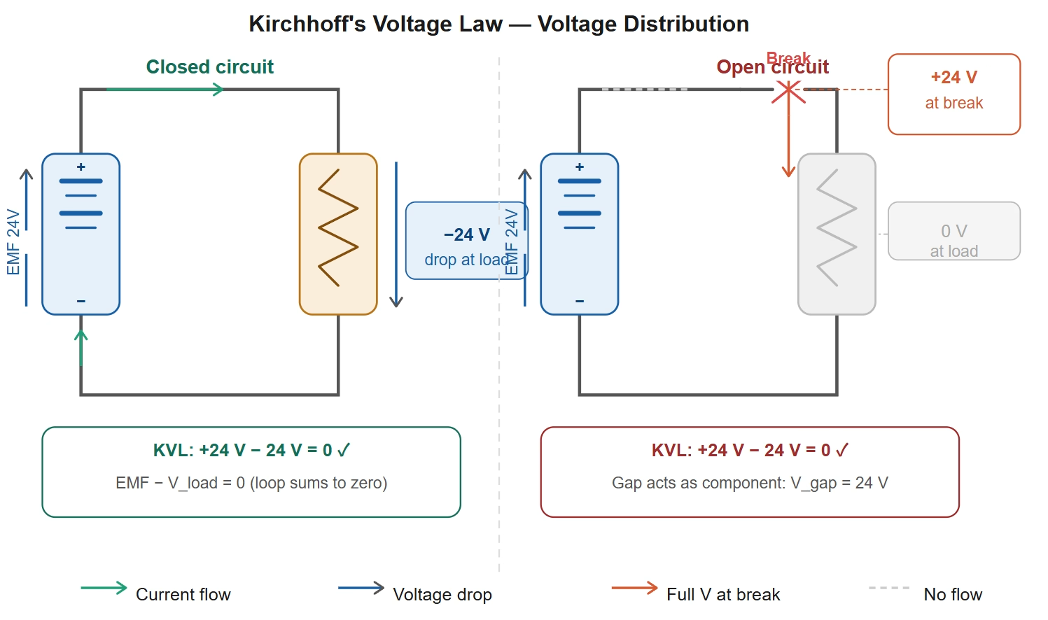
Kirchhoff’s Laws Applied to Both States
Kirchhoff’s Current Law (KCL) states that the sum of currents entering any node equals the sum leaving it. In an open circuit, one branch current becomes zero; KCL still holds, but the branch equations simplify dramatically — which is exactly how you identify which leg has failed.
Kirchhoff’s Voltage Law (KVL) states that the algebraic sum of voltages around any closed loop equals zero. Even in an open circuit, KVL remains valid: the open gap behaves like a component whose voltage drop equals the full supply, so the loop sum still reaches zero. This is precisely why you measure the full source voltage across an open break — the law demands it.
9. Circuit State Effects on Component Longevity
Beyond immediate function, whether a circuit is open or closed — and especially how abruptly it transitions between states — has lasting consequences for component lifespan. Understanding these effects helps engineers design for durability and technicians anticipate failure modes before they escalate.
Hazards of Unplanned Open Transitions
Suddenly opening a circuit that contains inductive loads — motors, relay coils, solenoids, or transformer primaries — forces the stored magnetic energy to discharge almost instantaneously. Because the inductor attempts to maintain its current through the now-broken path, it generates a high-voltage spike (back-EMF) that can greatly exceed the normal supply voltage. Without adequate protection, this transient can puncture the gate oxide of a MOSFET, destroy a driver IC, or char a PCB trace.
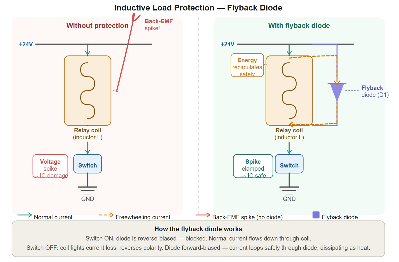
Standard mitigation techniques include flyback diodes across relay coils and DC motor terminals, TVS (transient voltage suppression) diodes for fast clamping, RC snubber networks across switch contacts, and varistors (MOVs) at AC-powered inductive loads. Selecting the right protection depends on the load’s inductance, switching speed, and the supply voltage.
Mechanical contacts also suffer when a circuit opens under load: the arc formed as the gap widens deposits carbon on contact surfaces, increasing contact resistance over time and eventually causing intermittent operation or welding of the contacts in the closed position.
Hazards of Prolonged or Unintended Closed States
A circuit that remains closed longer than its design intent accumulates heat. Components rated for intermittent duty — such as certain relay coils, solenoid valves, or small motors — can enter thermal runaway if the circuit never opens to allow cooling. The resulting damage is often irreversible and may not be immediately visible.
Battery-operated systems face an additional risk: unintended parasitic current paths (for example, through a leaky component or an undiscovered short) keep a closed circuit active during storage or standby, slowly draining the cells below their safe discharge threshold. Deep-discharging lithium-based cells in particular can permanently reduce capacity and, in severe cases, pose a safety hazard.
Characteristic Failure Modes by Circuit State
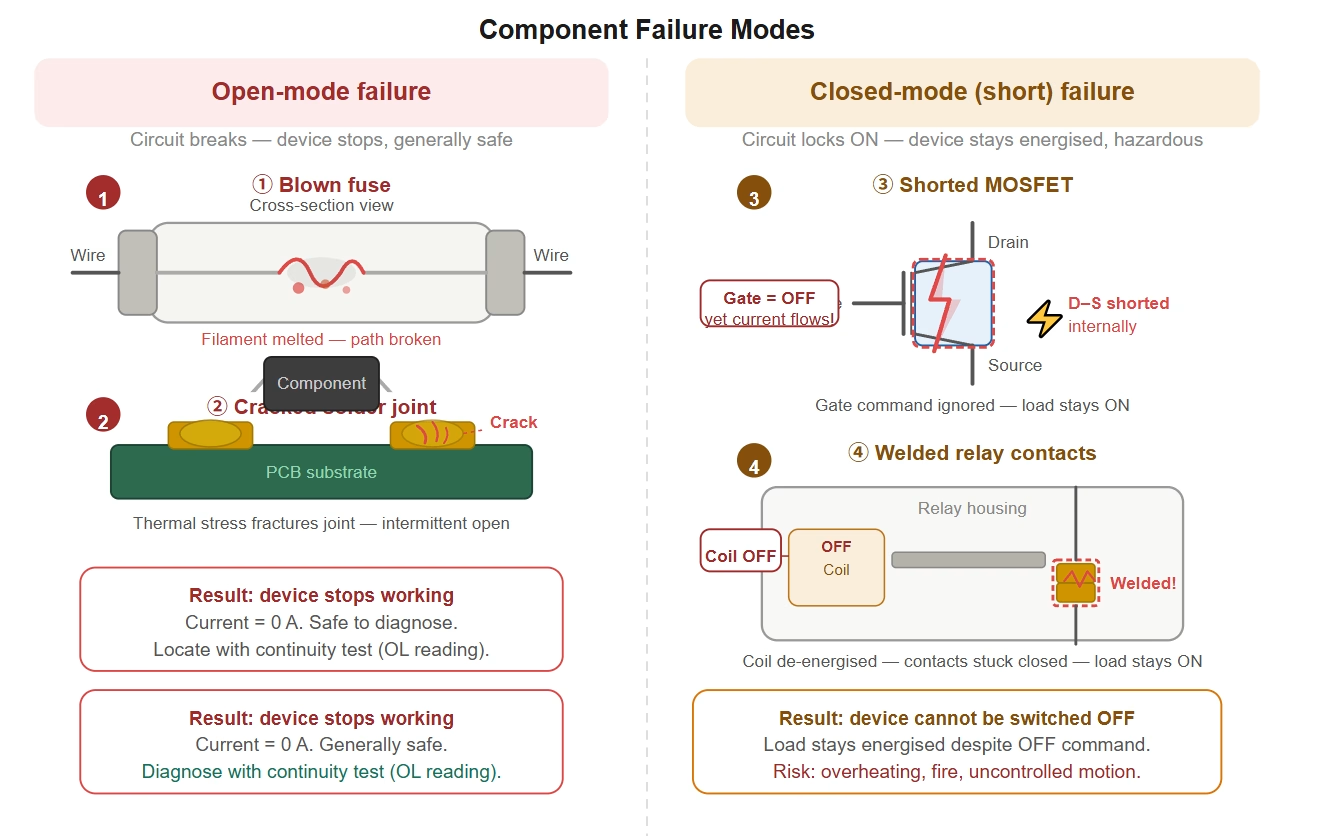
- Open-mode failures:Blown fuses, cracked solder joints, fractured PCB traces, and corroded terminals all leave the circuit permanently open. These failures are generally safe (the device simply stops working) but can be elusive to locate, especially when intermittent mechanical stress is the root cause.
- Closed-mode (short) failures:A shorted MOSFET or welded relay contact locks the circuit closed regardless of control signals. These failures are more hazardous: the load may remain energised even after a commanded shutdown, creating unexpected motion, heat, or fire risk. Always verify the actual state of the circuit — not just the control signal — before assuming a safe condition.
10. Design Best Practices for Reliable Circuits
Good circuit design anticipates both states and engineers graceful behaviour in each. The following practices address the most common causes of premature failure and unexpected transitions.
Fail-Safe Contact Selection (NC vs NO)
The choice between normally-closed (NC) and normally-open (NO) contacts defines what happens when wiring is accidentally severed. For life-safety systems — emergency stops, safety gates, fire suppression triggers — NC wiring ensures that a broken conductor produces an open circuit and therefore stops the machine. This fail-safe principle means the system defaults to a safe state without any active logic intervention.
Conversely, use NO contacts where inadvertent energisation would be the greater hazard — for instance, a solenoid valve controlling a high-pressure line that must remain closed until explicitly commanded open.
Connector and Mechanical Integrity
Intermittent open-circuit faults are most frequently traced to connectors that work loose under vibration or thermal cycling. Specifying locking connectors (such as latching Molex, WAGO lever-clamp, or M12 industrial types) rather than friction-fit headers dramatically reduces this failure mode. Where cables exit enclosures, stress-relief clamps and grommets prevent the conductor from flexing at the termination point — the location most vulnerable to fatigue fracture.
Corrosion Prevention
Oxidation builds resistance at contact surfaces, gradually transforming a reliably closed circuit into an intermittent or permanently open one. In high-humidity or outdoor environments, apply conformal coating to PCBs to block moisture ingress. Use IP-rated cable glands and silicone gaskets on enclosure penetrations. In industrial installations, gold- or silver-plated contacts in connectors significantly extend service life compared to bare copper or tin.
Over-Current Protection Sizing
Fuses and circuit breakers should be rated at approximately 125% of the expected steady-state current. This margin accommodates start-up inrush and normal variation without nuisance tripping, while still opening the circuit before sustained overcurrent causes thermal damage. For motor branches, verify that the protection device can handle the motor’s locked-rotor current during start-up before clearing to its running value.
Self-resetting thermistors (PTCs) placed near motors or transformers provide an additional thermal layer: they increase resistance sharply as temperature rises, effectively opening the circuit before the component reaches a destructive temperature, then automatically resetting once cool.
Redundancy for Critical Closed-Circuit Applications
Where an open-circuit event would be unacceptable — life-support equipment, data-centre power distribution, continuous process plants — provide parallel current paths so the system remains energised even if one conductor fails. Common implementations include dual-feeder UPS arrangements, ring-topology industrial Ethernet (so a break at any point still leaves all nodes connected), and redundant relay contacts wired in parallel to carry the load if one contact opens unexpectedly.
Proactive Monitoring and Maintenance
Modern systems increasingly use continuity-monitoring relays or loop-resistance measurement modules that signal a controller when resistance begins to climb — long before an intermittent open becomes a permanent one. Pairing this with periodic manual checks during scheduled shutdowns (inspect connectors, look for thermal discolouration, verify fuse integrity) creates a layered maintenance strategy that reduces unplanned downtime.
Clear, permanent wire labelling and up-to-date circuit documentation are equally important: when an open-circuit fault occurs at 2 a.m., a technician who can trace a numbered wire back to its schematic in seconds will restore the system far faster than one working from memory.
11. FAQ
Q: What is the main difference between an open and a closed circuit in terms of current?
A: In an open circuit, there is no current flow because the path is broken. In a closed circuit, current flows continuously because the path is complete.
Q: Can an open circuit still have voltage?
A: Yes, absolutely. While current cannot flow through the break, voltage from the power source can still be present across the break itself. This is critical for electrical safety, as parts of an open circuit can still be live.
Q: What happens if a closed circuit has too much current?
A: If a closed circuit has too much current (often due to an unintended “short circuit” where current bypasses the load through a low-resistance path), it can lead to overheating, component damage, blown fuses, tripped circuit breakers, and potential fire hazards. Proper circuit design and protection are essential.
Q: Is a switch considered an open or closed circuit?
A: A switch can create both. When a switch is “off,” it creates an open circuit, breaking the path. When it’s “on,” it creates a closed circuit, completing the path.
Q: Will an open circuit damage my components?
A: In a purely resistive circuit (LEDs, simple heaters, resistive loads), an open circuit causes the device to stop working but causes no physical damage. In circuits with inductive loads — motors, relay coils, solenoids — a sudden open can generate a large voltage spike (back-EMF) that may destroy semiconductor components or driver chips. Always fit appropriate suppression (flyback diode, TVS, or snubber) on inductive loads before opening the circuit under power.
Q: What is the difference between an open circuit and a short circuit?
A: They are opposite extremes of resistance. An open circuit has effectively infinite resistance at the break, so current is zero. A short circuit has near-zero resistance along an unintended path, so current rises to a dangerously high level limited only by the source impedance. Both prevent the load from working correctly, but a short circuit carries a much greater risk of fire, melted wiring, or component destruction.
Q: Do open and closed circuit rules apply to AC systems as well as DC?
A: Yes. The fundamental requirement — a complete, unbroken path for current to flow — applies equally to AC and DC. When an AC conductor breaks, circuit impedance becomes infinite and current drops to zero regardless of frequency. The key difference in AC analysis is that reactive components (capacitors, inductors) contribute impedance (Z) rather than pure resistance, but the open-circuit outcome is the same: no current flows.
Q: When should I use normally-closed (NC) versus normally-open (NO) contacts in my design?
A: Use NC contacts wherever a broken wire must produce a safe stop — emergency-stop buttons, safety interlock gates, and fire-suppression triggers are classic examples. If the conductor is accidentally severed, the circuit opens and the machine halts. Use NO contacts where unintentional energisation is the greater danger — for example, a solenoid on a high-pressure valve that must remain de-energised unless explicitly commanded. The governing principle is: ask which open-circuit state (energised or de-energised) is safer for your application, then wire accordingly.
12. Summary
The distinction between an open and a closed circuit is foundational to understanding electricity and electronics. A closed circuit offers a complete path for current flow, allowing electronic devices to function by converting electrical energy into useful work. Conversely, an open circuit has a break, preventing current from flowing, even if voltage is present. Mastering these concepts is not just theoretical; it’s a practical necessity for effective troubleshooting, robust circuit design, and ensuring paramount electrical safety. By understanding how current, voltage, and resistance behave in each state, you gain the ability to diagnose problems faster, design more reliable systems, and operate safely in any electrical environment.


