New title

<h1> Digital Isolators </h1> <p> Digital isolators are electronic components that transmit signals through optical, magnetic, or capacitive coupling technologies. They provide electrical isolation between systems with different voltages or grounds, ensuring data accuracy and system security. </p> <h2> 1. What are the Core Functions of Digital Isolators? </h2> <p> <strong>Electrical Isolation and Safety Protection</strong> </p> <p> Isolating high- and low-voltage circuits, they prevent damage from power supply fluctuations and electrostatic discharge (ESD) to low-voltage circuits, with an isolation voltage of up to 5000 VRMS. </p> <p> <strong>Interference Immunity</strong> </p> <p> Suppresses electromagnetic interference (EMI) and noise, ensuring signal stability, with a typical common-mode transient immunity (CMTI) of ±100 kV/μs. </p> <p> <strong>High-Speed Signal Transmission</strong> </p> <p> Supporting data rates of 100 Mbps to 150 Mbps, far exceeding traditional optocouplers, they are suitable for real-time control systems. </p> <h2> 2. What are the Types and Principles of Digital Isolators? </h2> <table> <tbody> <tr class="firstRow"> <td width="87" valign="top" style="padding: 0px 7px; border-width: 1px; border-color: windowtext; background: rgb(190, 190, 190);"> <p> Type </p> </td> <td width="291" valign="top" style="padding: 0px 7px; border-width: 1px; border-color: windowtext; background: rgb(190, 190, 190);"> <p> Working Principle </p> </td> <td width="189" valign="top" style="padding: 0px 7px; border-width: 1px; border-color: windowtext; background: rgb(190, 190, 190);"> <p> Features </p> </td> </tr> <tr> <td width="87" valign="top" style="padding: 0px 7px; border-left-width: 1px; border-left-color: windowtext; border-right-width: 1px; border-right-color: windowtext; border-top: none; border-bottom-width: 1px; border-bottom-color: windowtext;"> <p> Optocoupler Isolation </p> </td> <td width="291" valign="top" style="padding: 0px 7px; border-left-width: 1px; border-left-color: windowtext; border-right-width: 1px; border-right-color: windowtext; border-top: none; border-bottom-width: 1px; border-bottom-color: windowtext;"> <p> Input electrical signal → LED light signal → Photodetector → Output electrical signal. </p> </td> <td width="189" valign="top" style="padding: 0px 7px; border-left-width: 1px; border-left-color: windowtext; border-right-width: 1px; border-right-color: windowtext; border-top: none; border-bottom-width: 1px; border-bottom-color: windowtext;"> <p> Low cost, long lifespan; slow speed (<50 Mbps). </p> </td> </tr> <tr> <td width="87" valign="top" style="padding: 0px 7px; border-left-width: 1px; border-left-color: windowtext; border-right-width: 1px; border-right-color: windowtext; border-top: none; border-bottom-width: 1px; border-bottom-color: windowtext;"> <p> Magnetic Isolation </p> </td> <td width="291" valign="top" style="padding: 0px 7px; border-left-width: 1px; border-left-color: windowtext; border-right-width: 1px; border-right-color: windowtext; border-top: none; border-bottom-width: 1px; border-bottom-color: windowtext;"> <p> Signal transmission via magnetic field coupling, achieved through a transformer or inductor. </p> </td> <td width="189" valign="top" style="padding: 0px 7px; border-left-width: 1px; border-left-color: windowtext; border-right-width: 1px; border-right-color: windowtext; border-top: none; border-bottom-width: 1px; border-bottom-color: windowtext;"> <p> Long transmission distance; large size, weak resistance to magnetic interference. </p> </td> </tr> <tr> <td width="87" valign="top" style="padding: 0px 7px; border-left-width: 1px; border-left-color: windowtext; border-right-width: 1px; border-right-color: windowtext; border-top: none; border-bottom-width: 1px; border-bottom-color: windowtext;"> <p> Capacitive Isolation </p> </td> <td width="291" valign="top" style="padding: 0px 7px; border-left-width: 1px; border-left-color: windowtext; border-right-width: 1px; border-right-color: windowtext; border-top: none; border-bottom-width: 1px; border-bottom-color: windowtext;"> <p> Capacitive coupling technology with internal AC/DC dual-channel intelligent switching. </p> </td> <td width="189" valign="top" style="padding: 0px 7px; border-left-width: 1px; border-left-color: windowtext; border-right-width: 1px; border-right-color: windowtext; border-top: none; border-bottom-width: 1px; border-bottom-color: windowtext;"> <p> Excellent high-frequency performance (150 Mbps), low power consumption, and strong EMI immunity. </p> </td> </tr> </tbody> </table> <p>   </p> <h2> 3. What are the Key Application Scenarios of Digital Isolators? </h2> <p> <strong>1) Smart Home and Industrial Control</strong>: Isolates sensor and actuator signals, preventing ground loop interference and improving device reliability. </p> <p> <strong>2) New Energy Vehicles and Autonomous Driving</strong>: </p> <p> <strong>Battery Management System (BMS)</strong>: Ensures secure communication between high-voltage batteries and low-voltage control circuits. </p> <p> <strong>Motor Drive</strong>: Ensures delay-free transmission of power signals in traction inverters to prevent latch-up effects. </p> <p> <strong>3) Medical and Power Systems</strong>: Isolates patient circuits in devices such as electrocardiographs, enabling high-precision current/voltage measurement in power monitoring. </p> <h2> 4. Technology Evolution Trends of Digital Isolators </h2> <p> <strong>Integrated Design</strong>: Multi-channel isolators reduce external components and optimize PCB layout. </p> <p> <strong>Wireless Signal Isolation</strong>: New solutions (such as Silicon Labs' products) replace physical media with 2.4 GHz RF transmission, offering lower power consumption and higher speeds. </p> <p> <strong>Improved Reliability</strong>: Capacitive isolators address power-on surge issues and ensure correct signal polarity. </p> <p> Digital isolators are driving innovation in high-safety electronic systems, becoming a key enabling technology in autonomous driving, Industry 4.0, and energy sectors. </p> <p>
<h1> Isolators - Gate Drivers </h1> <p> Isolated gate drivers (Isolators) are key interface circuits in power electronics systems, primarily used to safely and efficiently drive power semiconductor devices (such as MOSFETs, IGBTs, SiC MOSFETs, and GaN HEMTs). Their core function is to convert the controller's low-power logic signals into high-current/high-voltage drive signals and achieve electrical isolation, ensuring safe separation between high-voltage power circuits and low-voltage control circuits. </p> <p>   </p> <h2> 1. What are the Core Functions and Technical Features of Isolators - Gate Drivers? </h2> <h3> 1) Signal Amplification and Drive Capability </h3> <p> They receive weak signals (typically 3.3V/5V) from a microcontroller and amplify them to drive voltages of 10V–30V. They provide transient currents ranging from hundreds of milliamperes to several amperes, rapidly charging and discharging the gate capacitance of power devices and achieving nanosecond switching speeds. </p> <p>   </p> <h3> 2) Electrical Isolation Mechanism </h3> <p> Through optocouplers, transformers, or capacitive coupling, they achieve electrical isolation of several thousand volts (e.g., 5kV) between the input and output terminals. The isolation barrier blocks common-mode noise, preventing high-voltage surges from damaging the controller while also improving the system's electromagnetic interference (EMI) immunity. </p> <p>   </p> <h3> 3) Protection and Stability Design </h3> <p> <strong>Protection Circuitry</strong>: Integrated undervoltage lockout (UVLO), overcurrent protection (DESAT), and Miller clamping prevent power device damage due to abnormal gate voltage or short circuits. </p> <p> <strong>Dead Time Control</strong>: Prevents shoot-through failures in upper and lower transistors in half-bridge topologies, optimizing switching efficiency. </p> <p>   </p> <h2> 2. What are the Application Scenarios of Isolators - Gate Drivers? </h2> <p> <strong>Electric Vehicles</strong>: Drive motor controllers, on-board chargers (OBCs), and DC-DC converters, supporting 800V high-voltage architectures. </p> <p> <strong>Photovoltaic Inverters</strong>: Control the switching of IGBT/SiC modules to achieve efficient DC-AC conversion. </p> <p> <strong>Industrial Motor Drives</strong>: Precisely control the torque and speed of three-phase motors and reduce harmonic distortion. </p> <p> <strong>UPS Power Supplies</strong>: Ensure fast switching of inverter modules and provide uninterrupted power. </p> <p>   </p> <h2> 3. Technology Evolution Trends of Isolators - Gate Drivers </h2> <p> <strong>Wide Bandgap Semiconductor Adaptation</strong>: The next-generation driver optimizes dv/dt withstand capability (>100V/ns) to match the ultra-high-speed switching characteristics of SiC/GaN devices. </p> <p> <strong>Highly Integrated Design</strong>: Monolithically integrates functions such as isolated power supply, protection circuits, and level shifting, reducing system size and simplifying PCB layout. </p> <p> <strong>Functional Safety Certification</strong>: Certified to ISO 26262 (automotive) or IEC 60730 (industrial), meeting the requirements of high-reliability scenarios. </p> <p>   </p> <p> As the "invisible commander" of the power conversion system, isolated gate drivers become core components for improving energy efficiency and reliability through precise gate control and strong electrical isolation. </p> <p>
<h1> Optoisolators </h1> <p> Optoisolators, also known as optocouplers or photocouplers, are electronic components that achieve electrical isolation based on optical signals. They use a combination of a light-emitting diode (LED) and a photosensor (such as a phototransistor or photodiode) to completely isolate the input circuit from the output circuit, allowing only one-way optical signal transmission, thereby preventing high voltage, noise, or interference from affecting the low-voltage system. </p> <p>   </p> <h2> 1. What are the Working Principles and Structure of Optoisolators? </h2> <p> <strong>Core Mechanism</strong>: When input current activates the LED, it emits infrared light. This light signal is transmitted through a transparent isolation layer to the photosensor, which converts the light energy into an electrical signal for output. This "electrical-optical-electrical" process ensures no direct electrical connection between the input and output circuits. The isolation resistance can exceed 10¹²Ω, effectively blocking transient interference up to 10kV. </p> <p> <strong>Internal Structure</strong>: Typically enclosed in a light-tight housing, it contains an LED light source and a photosensor (such as a phototransistor or thyristor). The isolation layer is composed of air, glass, or plastic, enabling low-loss signal transmission (typical loss ≤ 0.2dB). </p> <p>   </p> <h2> 2. What are the Core Functions of Optoisolators?  </h2> <p> <strong>‌Electrical Isolation‌</strong>: Separates high-voltage and low-voltage circuits, preventing high-voltage leakage into the low-voltage side, protecting sensitive components (such as MCUs), and serving as a "safety gate" in switching power supplies, inverters, and medical devices. </p> <p> <strong>‌Interference Immunity‌</strong>: The high internal resistance of interference sources prevents them from providing sufficient current to drive LEDs, blocking noise signals (such as electromagnetic interference) at the input, ensuring signal integrity and system reliability. </p> <p> <strong>‌Signal Transmission‌</strong>: Supports digital and analog signal transmission. Current Transfer Ratio (CTR) is a key parameter (typical CTR is 20-30%), affecting response speed and stability. CTR decreases in high-temperature environments, requiring design margins. </p> <p>   </p> <h2> 3. What are the Advantages and Disadvantages of Optoisolators? </h2> <p> <strong>‌Advantages‌</strong>: High isolation (up to 63dB), fast response, compact size (miniaturized diameter 3-4mm), and suitable for wide operating temperatures (-20°C to +70°C). </p> <p> <strong>Disadvantages</strong>: LED drive current is low, making them susceptible to low-power interference and requiring software noise filtering. Traditional devices rely on temperature control, but integrated approaches (such as magneto-optical photonic crystals) are addressing these size and dependency issues. </p> <p>   </p> <h2> 4. What are the Types of Optoisolators? </h2> <p> Common types include phototransistors (such as the 4N35, used for general signal isolation), Darlington diodes (with a CTR of up to 500%, amplifying weak signals), photothyristors (such as the MOC3071, controlling AC circuits), and optical isolators (specifically for use in the 1310nm-1550nm optical fiber communication band). </p> <p>   </p> <h2> 5. What are the Applications of Optoisolators? </h2> <p> <strong>Power Supply Isolation</strong>: Prevents power supply interference when input and output voltages are inconsistent, protecting circuit boards (such as modems and lightning arresters). </p> <p> <strong>Communication Systems</strong>: Prevents optical feedback in optical fiber amplifiers and lasers, ensuring unidirectional transmission; and filters atmospheric interference in data transmission, such as in CAN buses. </p> <p> <strong>Industrial Control</strong>: Isolates high dV/dt noise in inverters and PLC systems, reducing the error rate (case studies have shown this can be reduced to 0.3%). </p> <p> <strong>Level Conversion</strong>: Enables passive conversion between 3.3V and 5V systems with microsecond latency. </p> <p>   </p> <p>
<h1> Special Purpose Isolators </h1> <p> Special purpose isolators use one- and two-channel optoelectronic circuits to perform specific tasks such as I2C repeaters, line receivers, current loop receivers and transmitters, optical power converters, photocell optocouplers, power MOSFETs, and power transistor drivers. Mounting types include surface, through-hole and free-hanging. Voltage supply and output current are among the key differentiation parameters. </p> <p>

Isolators

‌Isolators‌ are key components used to achieve electrical isolation in electronic circuits. Their main function is to block direct electrical connections between different circuits while allowing unidirectional transmission of signals or energy, thereby improving the safety and anti-interference ability of the system. The following is a detailed description of its core features and application scenarios:

‌1. Isolators Overview‌

1)‌Basic composition‌

Usually composed of optical couplers‌ or ‌transformers‌, and some high-frequency scenarios use RF-specific structures‌.

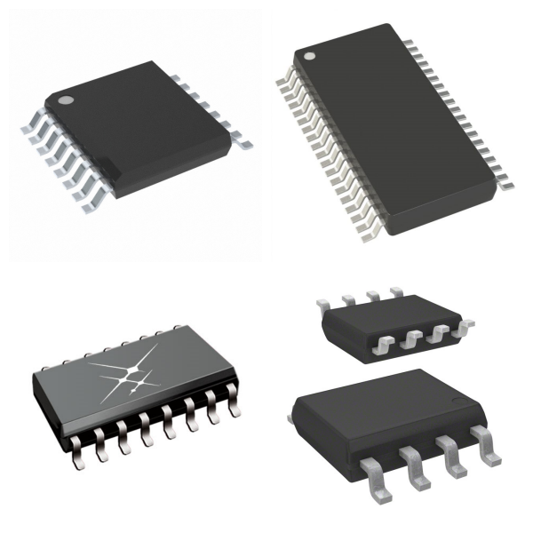
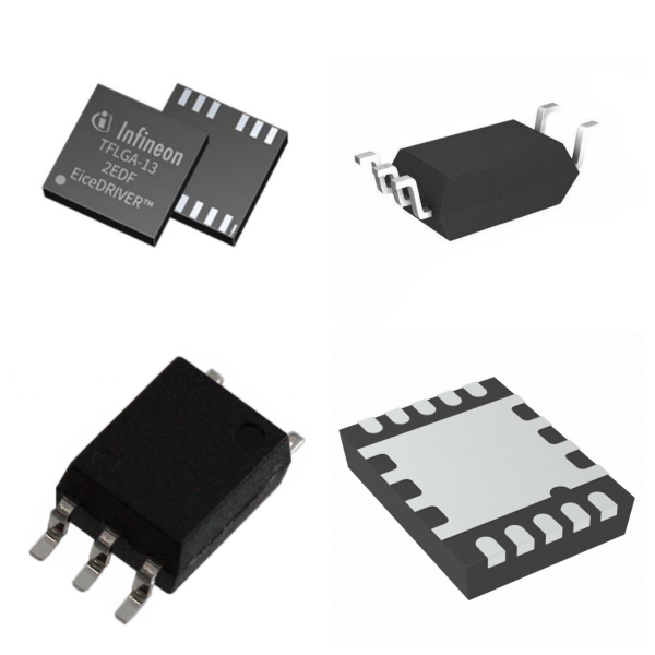
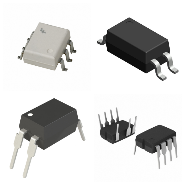
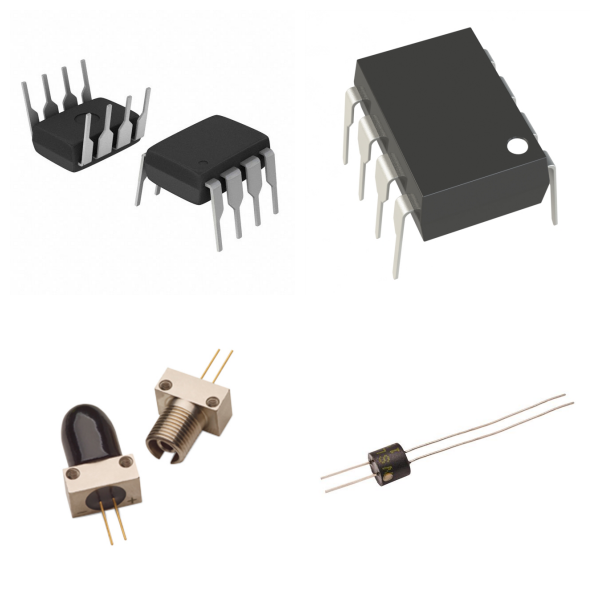
There are various packaging forms, such as direct plug-in type, surface mount type (SMD), etc. Some high-end models use ‌hermetic packaging‌ to enhance weather resistance‌.

2)‌Core functions‌

‌Electrical isolation‌: Isolate high-voltage and low-voltage circuits to prevent abnormal current flow from causing damage to equipment or personnel‌.

‌Signal transmission‌: Realize cross-isolation transmission of signals through electromagnetic induction or photoelectric conversion to avoid ground loop interference‌.

‌Decoupling and filtering‌: Separate DC components and AC noise in the power supply circuit to improve system stability‌.

‌2. What are Isolators Used for?‌

‌Power supply and industrial system

Decoupling circuit for power module to suppress high-frequency noise interference‌.

Isolate control circuits and execution circuits in industrial automation equipment to prevent high-voltage shock from damaging sensitive components‌.

‌Communication and RF field

RF isolators (such as ‌MACOM MADL series‌) are used in high-frequency systems such as wireless communication and radar, supporting ‌1 GHz to 2 GHz‌ frequency bands, with an impedance of ‌50Ω‌ to ensure the stability of signal transmission‌.

Protect the front-end circuit of the receiver to avoid equipment damage caused by signal reflection‌.

‌Medical and precision equipment

Isolate the patient side from the main control circuit in medical equipment to ensure safety and compliance‌.

Block common-mode interference in precision measuring instruments to improve signal acquisition accuracy‌.

‌3. How to Choose Isolators?‌

1)‌Key parameters‌

‌Frequency range‌: For example, the RF isolator needs to match the system operating frequency band (such as 1.3 GHz)‌. ‌Insertion loss‌: Typical value is as low as ‌0.35 dB‌, reducing signal attenuation‌.

‌Temperature resistance‌: The operating temperature range is usually ‌-65°C to 125°C‌.

2)‌Classification and selection recommendations‌

‌Photoelectric coupling type‌: Suitable for low-frequency signal isolation, and low cost‌.

‌Transformer coupling type‌: Supports high frequency and energy transmission, but has a larger volume‌.

‌RF dedicated type‌: Optimized for high-frequency scenarios, attention should be paid to impedance matching and packaging form‌.

4. Typical Brands for Isolators

Infineon

TOSHIBA

Onsemi

TI

VISHAY

LITEON

5. Isolators FAQs

1) How do Isolators work? ‌

‌Photocoupler‌: The input LED emits light, and the photosensitive element (such as a phototransistor) receives the light signal and converts it into an electrical signal, realizing no direct electrical connection between the input and the output‌.

‌Capacitive Isolator‌: Through high-frequency signal modulation, energy or data is transferred using the capacitor medium, blocking DC and low-frequency interference‌.

‌Inductive Isolator‌: Energy or signal is transferred using magnetic field coupling, isolating the primary and secondary circuits‌.

‌2) What are the common failure mechanisms of Isolators and how to avoid them? ‌

‌Optical Attenuation of Optocouplers‌: LED aging causes signal transmission failure, so it is necessary to select high-reliability models and avoid long-term overload‌.

‌Capacitive Isolation Breakdown‌: Overvoltage or dielectric aging causes short circuits, so it is necessary to strictly limit the operating voltage and add protection circuits‌.

‌Inductive Isolation Saturation‌: The magnetic field is too strong, resulting in a decrease in efficiency, and the core material and drive current need to be optimized‌.

‌3) How to determine whether the isolation level of Isolators meets the requirements? ‌

The isolation level needs to be comprehensively evaluated based on the system's maximum operating voltage, transient overvoltage (such as lightning strikes or switching surges), and safety standards (such as IEC 61010). For example, medical equipment usually requires reinforced isolation (such as 5000Vrms), while industrial control scenarios may only require basic isolation (2500Vrms).

4) What factors affect the life of isolators? ‌

‌Optocoupler‌: LED light decay is the main factor. Long-term high temperature or overcurrent will accelerate aging. It is recommended to control the forward current within 60% of the rated value.

‌Capacitive Isolator‌: The aging of the dielectric material or moisture penetration may cause capacitance drift. Moisture-resistant packaging (such as ceramic dielectric) is required.

‌Solid-State Relay‌: The number of switching times and load type (capacitive/inductive) affect the contact life. The life under resistive load can reach more than 10^7 times.

5) What are the common design issues of isolators in I2C communication? ‌

‌Bidirectional Signal Conflict‌: Direct use of unidirectional isolators will cause bus latch failure. It is necessary to select a dedicated isolation I2C chip (such as ISO1540) or implement bidirectional isolation through an external logic circuit‌.

‌Signal Delay‌: The transmission delay of the isolation device must be less than the minimum clock cycle of the I2C bus. For example, a 100kHz bus requires a delay of ≤ 1μs‌.

‌Power Consumption Matching‌: The pull-up resistor values on both sides of the isolator must match the bus driving capability to avoid abnormal logic levels due to impedance mismatch‌.

‌6) What is the difference between isolators and other protection devices (such as TVS diodes)? ‌

‌Functional Difference‌: Isolators achieve electrical isolation and block common-mode interference and ground loops; TVS diodes are mainly used to suppress transient overvoltages (such as ESD) and belong to clamping protection‌.

‌Application Scenarios‌: Isolators are suitable for long-term isolation needs (such as power systems), while TVS diodes are used for short-term pulse protection (such as communication ports)‌.

‌Cooperative Use‌: In a high-voltage environment, isolators and TVS diodes can be connected in series, the former isolating continuous interference, and the latter absorbing transient energy‌.

7) How to test the isolation performance of isolators? ‌

‌Withstand Voltage Test‌: Use a withstand voltage tester to apply isolation voltage (such as 3000Vrms/1 minute) to detect whether the leakage current exceeds the standard (usually ≤ 1mA)‌.

‌Transmission Characteristics Test‌: Input a square wave through a signal generator, and observe the waveform distortion and delay at the output end with an oscilloscope to verify whether the bandwidth meets the standard‌.

‌Temperature Rise Test‌: Continuously operate at the highest operating temperature to monitor whether the isolation medium has a breakdown or parameter drift‌.

‌6. Summary‌

Isolators ensure circuit safety and signal integrity through physical isolation and are indispensable components in power supply, communication, industry, and medical fields. When selecting, it is necessary to consider the frequency requirements, isolation strength, and packaging form.