<h1> Attenuators </h1> <h2> 1. What are Attenuators? </h2> <p> An attenuator is an electrical device that reduces signal power without degrading signal integrity. Simply put, an electrical/electronic attenuator is a device that reduces the amount of electrical/electronic energy passing through it by diverting some of the energy to a heat source or ground. </p> <p> </p> <h2> 2. How do Attenuators Work? </h2> <p> An attenuator works by providing an impedance-matching network between the signal source and the load, reducing the signal amplitude by absorbing some of the signal energy. The amount of attenuation is determined by the ratio of the input impedance to the output impedance. </p> <p> </p> <h2> 3. What are the Types of Attenuators? </h2> <p> Fixed Attenuator </p> <p> Variable Attenuator </p> <p> Switchable Attenuator </p> <p> Step Attenuator </p> <p> </p> <h2> 4. What are Attenuators Used for? </h2> <p> Attenuators are used to adjust the level of audio and RF signals and are essential in any sound system that requires a properly balanced sound. Attenuators are also used in electronic circuits to reduce the signal level without changing the signal waveform. </p>
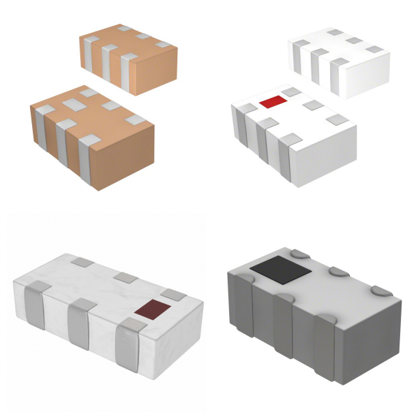
<h1> Balun </h1> <p> A balun is a three-port passive device designed for converting balanced and unbalanced signals. Its core functions include interface conversion between differential and single-ended signals, impedance matching, and common-mode noise suppression. </p> <p> </p> <h2> 1. What are the Basic Functions of Balun? </h2> <p> <strong>Signal Conversion</strong>: Converts single-ended unbalanced signals (such as coaxial cables) to differential balanced signals (such as twisted pair cables), and vice versa. </p> <p> </p> <p> <strong>Impedance Matching</strong>: Optimizes power transfer between circuits with different impedances by using specific impedance ratios (such as 1:1, 1:2, and 4:1). </p> <p> </p> <p> <strong>Noise Suppression</strong>: Reduces common-mode interference through the common-mode rejection ratio (CMRR), improving the system's interference immunity. </p> <p> </p> <h2> 2. What are the Key Performance Indicators of Balun? </h2> <p> <strong>Frequency Range</strong>: Determines the applicable operating frequency band for the balun. </p> <p> </p> <p> <strong>Insertion Loss (IL)</strong>: The power loss of the signal passing through the balun must be as low as possible. </p> <p> </p> <p> <strong>Amplitude and Phase Balance</strong>: The amplitude difference and the degree to which the phase deviates from 180° in the differential output directly affect signal quality. </p> <p> </p> <p> <strong>Common-Mode Rejection Ratio (CMRR)</strong>: Measures the ability to reject common-mode signals. </p> <p> </p> <h2> 3. What are the Common Types of Balun? </h2> <p> <strong>Flux-Coupled Transformer Balun</strong>: Achieves signal conversion through magnetic core coupling and is suitable for high-frequency circuits. </p> <p> </p> <p> <strong>Transformer Balun</strong>: Uses independent coil windings to provide electrical isolation and is suitable for applications with grounding issues. </p> <p> </p> <p> <strong>Transmission Line Balun</strong>: Uses windings of a transmission line to achieve impedance transformation and is commonly used in broadband applications. </p> <p> </p> <h2> 4. What are the Typical Application Scenarios of Balun? </h2> <p> <strong>Communication Systems</strong>: RF front-end signal processing in mobile phones and routers. </p> <p> </p> <p> <strong>RF Circuits</strong>: Signal adaptation between power amplifiers (PAs) and antennas. </p> <p> </p> <p> <strong>Long-Distance Transmission</strong>: Interfaces between balanced transmission lines and unbalanced signal sources. </p> <p> </p> <p> The design and selection of baluns must comprehensively consider factors such as frequency characteristics, impedance matching, and environmental noise to ensure optimal system performance. </p>
<h1> RF Accessories </h1> <p> The RF accessory family contains products incidental, supplementary, or supportive of other radio related products, including SIM cards, adapter cables, antenna mounting bases and mounting brackets, hardware, surge protection modules for RF (antenna) cables, programming and configuration tools, OEM power adapters and cable sets, antenna covers, and others. </p>
<h1> RF Amplifiers </h1> <h2> 1. What are RF Amplifiers? </h2> <p> RF amplifiers are electronic devices designed to process high-frequency signals (typically in the 30MHz to 6GHz band). They are powered by an external power supply to amplify signal power and are widely used in communications systems, radar equipment, medical imaging, and test and measurement instruments. Based on the operating frequency band, they can be categorized as narrowband (such as those specifically designed for the LTE band) and wideband (such as those for general use between 2 and 18GHz). </p> <p> </p> <h2> 2. What are the Key Parameters of RF Amplifiers? </h2> <p> <strong>Gain</strong>: A typical value of 20-50dB, characterizing signal amplification capability. </p> <p> <strong>Linearity</strong>: Measured by OIP3 (third-order intercept point), which affects signal fidelity. </p> <p> <strong>Noise Figure (NF)</strong>: High-end models with as low as 0.5dB improve receiver sensitivity. </p> <p> <strong>Input/Output Impedance</strong>: Typically designed to 50Ω to match standard RF systems. </p> <p> </p> <h2> 3. Technological Evolution of RF Amplifiers </h2> <p> <strong>GaN (Gallium Nitride) Technology</strong>: Breaks through the limitations of traditional LDMOS technology, achieving higher power density and high-temperature resistance. </p> <p> <strong>Integration Trend</strong>: Modern SoC solutions integrate driver circuits with amplifiers to reduce external components. </p> <p> </p> <h2> 4. What are the Application Scenarios of RF Amplifiers? </h2> <table> <tbody> <tr class="firstRow"> <td width="142" valign="top" style="padding: 0px 7px; border-width: 1px; border-color: windowtext; background: rgb(190, 190, 190);"> <p> Field </p> </td> <td width="186" valign="top" style="padding: 0px 7px; border-width: 1px; border-color: windowtext; background: rgb(190, 190, 190);"> <p> Typical Applications </p> </td> <td width="241" valign="top" style="padding: 0px 7px; border-width: 1px; border-color: windowtext; background: rgb(190, 190, 190);"> <p> Special Requirements </p> </td> </tr> <tr style="height:32px"> <td width="142" valign="top" style="padding: 0px 7px; border-left-width: 1px; border-left-color: windowtext; border-right-width: 1px; border-right-color: windowtext; border-top: none; border-bottom-width: 1px; border-bottom-color: windowtext;"> <p> 5G Base Stations </p> </td> <td width="186" valign="top" style="padding: 0px 7px; border-left-width: 1px; border-left-color: windowtext; border-right-width: 1px; border-right-color: windowtext; border-top: none; border-bottom-width: 1px; border-bottom-color: windowtext;"> <p> Massive MIMO Arrays </p> </td> <td width="241" valign="top" style="padding: 0px 7px; border-left-width: 1px; border-left-color: windowtext; border-right-width: 1px; border-right-color: windowtext; border-top: none; border-bottom-width: 1px; border-bottom-color: windowtext;"> <p> High Linearity, Low Phase Noise </p> </td> </tr> <tr> <td width="142" valign="top" style="padding: 0px 7px; border-left-width: 1px; border-left-color: windowtext; border-right-width: 1px; border-right-color: windowtext; border-top: none; border-bottom-width: 1px; border-bottom-color: windowtext;"> <p> Satellite Communications </p> </td> <td width="186" valign="top" style="padding: 0px 7px; border-left-width: 1px; border-left-color: windowtext; border-right-width: 1px; border-right-color: windowtext; border-top: none; border-bottom-width: 1px; border-bottom-color: windowtext;"> <p> Uplink Amplification </p> </td> <td width="241" valign="top" style="padding: 0px 7px; border-left-width: 1px; border-left-color: windowtext; border-right-width: 1px; border-right-color: windowtext; border-top: none; border-bottom-width: 1px; border-bottom-color: windowtext;"> <p> Radiation-Hardened Design </p> </td> </tr> <tr style="height:38px"> <td width="142" valign="top" style="padding: 0px 7px; border-left-width: 1px; border-left-color: windowtext; border-right-width: 1px; border-right-color: windowtext; border-top: none; border-bottom-width: 1px; border-bottom-color: windowtext;"> <p> Automotive Radar </p> </td> <td width="186" valign="top" style="padding: 0px 7px; border-left-width: 1px; border-left-color: windowtext; border-right-width: 1px; border-right-color: windowtext; border-top: none; border-bottom-width: 1px; border-bottom-color: windowtext;"> <p> 77 GHz Band </p> </td> <td width="241" valign="top" style="padding: 0px 7px; border-left-width: 1px; border-left-color: windowtext; border-right-width: 1px; border-right-color: windowtext; border-top: none; border-bottom-width: 1px; border-bottom-color: windowtext;"> <p> Wide Temperature Stability </p> </td> </tr> </tbody> </table> <p> </p> <h2> 5. Selection Recommendations for RF Amplifiers </h2> <p> Prioritize the compatibility of the operating frequency band with system requirements. </p> <p> High-power applications require attention to thermal management design (e.g., copper-based packaging). </p> <p> Medical equipment must comply with FCC/CE electromagnetic compatibility standards. </p>
<h1> RF Antennas </h1> <p> Radio frequency antennas (RF antennas) are key components for transmitting and receiving wireless signals, enabling long-distance data transmission through electromagnetic wave conversion. Modern technology enables them to cover a wide frequency band, from MHz to GHz, making them suitable for cutting-edge fields such as 5G, the Internet of Things (IoT), and satellite communications. </p> <p> </p> <h2> 1. What are the Core Technical Parameters of RF Antennas? </h2> <p> <strong>Frequency Range</strong>: Customized design meets requirements from Sub-6GHz to millimeter wave frequency bands. </p> <p> <strong>Gain</strong>: Adjustable from 3-15dBi to ensure directional signal transmission efficiency. </p> <p> <strong>Polarization</strong>: Supports linear and circular polarization, adaptable to complex environments. </p> <p> <strong>Impedance Matching</strong>: Standard 50Ω interface, compatible with mainstream RF circuits. </p> <p> </p> <h2> 2. What are the Typical Application Scenarios of RF Antennas? </h2> <p> <strong>Smart Home</strong>: Wi-Fi 6E router antenna array. </p> <p> <strong>Industrial IoT</strong>: LoRaWAN wide-area network coverage antenna. </p> <p> <strong>In-Vehicle Communications</strong>: V2X high-gain antenna module. </p> <p> </p> <h2> 3. Selection Recommendations for RF Antennas </h2> <p> Select the gain level based on the transmission distance (<5dBi indoors, >8dBi outdoors). </p> <p> Circularly polarized antennas are preferred in multipath interference environments. </p> <p> Radiation efficiency must be verified through OTA testing (≥70%). </p> <p> </p> <h2> 4. Technology Development Trends of RF Antennas </h2> <p> Phased array antennas and MIMO (Multi-Input, Multiple-Output) technology are driving antennas towards miniaturization and intelligence. By 2025, the next generation of ceramic dielectric antennas will reduce power consumption by 30%. </p>
<h1> RF Circulators and Isolators </h1> <p> RF circulators and isolators are key passive components in radio frequency (RF) and microwave systems, primarily used to achieve unidirectional signal transmission and path isolation. They are widely used in radar, communication systems, and quantum computing. </p> <p> </p> <h2> 1. What are the Basic Principles of RF Circulators and Isolators? </h2> <p> <strong>Circulator</strong>: Typically a three-port device, it uses ferromagnetic materials to achieve directional transmission of RF power from port 1 to port 2, port 2 to port 3, and port 3 to port 1, while also isolating the signal in the reverse direction. Its ideal scattering matrix exhibits nonreciprocity, preventing reverse signal transmission. </p> <p> </p> <p> <strong>Isolator</strong>: Essentially a two-port circulator, it terminates one port to achieve unidirectional transmission. It offers low forward insertion loss (e.g., <0.5 dB) and high reverse loss (>20 dB), and is used to protect sensitive devices from reflection interference. </p> <p> </p> <h2> 2. What are the Types of RF Circulators and Isolators? </h2> <p> <strong>Circulator Types</strong>: Include Y-junction circulators, differential phase-shift circulators, and Faraday rotation circulators. Y-junction circulators are the most widely used in waveguide and microstrip lines. </p> <p> </p> <p> <strong>Isolator Design</strong>: Relying on the choice of ferromagnetic materials and topology, nonreciprocity is achieved through a static magnetic field. </p> <p> </p> <h2> 3. What are the Application Scenarios of RF Circulators and Isolators? </h2> <p> Circulators are often used in duplexer designs to support simultaneous transmission and reception (such as in radar and communications systems). </p> <p> </p> <p> Isolators are primarily used to stabilize signal source frequencies and isolate high-power reflections. </p> <p> </p> <h2> 4. What are the Technical Parameters of RF Circulators and Isolators? </h2> <p> Key performance indicators include insertion loss, isolation, power handling capability, and bandwidth. For example, DiTom brand circulators can operate in cryogenic environments and are suitable for quantum computing. </p>
<h1> RF Demodulators </h1> <p> RF demodulators are key components in wireless communication systems, primarily used to extract the original information from the carrier signal. </p> <p> </p> <h2> 1. What are the Core Functions of RF Demodulators? </h2> <p> A demodulator detects and processes the modulated RF signal to recover the modulated baseband signal (such as audio or data). In a superheterodyne receiver, it is typically located between the intermediate frequency amplifier and the audio amplifier, converting the signal from high frequency to low frequency. </p> <p> </p> <h2> 2. What are the Technical Classification of RF Demodulators? </h2> <p> <strong>AM Demodulation</strong>: Uses an envelope detector (such as a diode detector circuit) to extract amplitude-modulated signals. </p> <p> <strong>FM/PM Demodulation</strong>: Detects frequency or phase changes using a frequency discriminator or phase-locked loop (PLL). </p> <p> <strong>Digital Demodulation</strong>: Applicable to digital modulation schemes such as ASK and FSK, and is commonly used in IoT and RFID applications. </p> <p> </p> <h2> 3. What are the Typical Application Scenarios of RF Demodulators? </h2> <p> <strong>Broadcast Systems</strong>: Signal demodulation in AM/FM radios. </p> <p> <strong>Communications Equipment</strong>: Baseband signal recovery in mobile phones and Bluetooth modules. </p> <p> <strong>Industrial Control</strong>: Data extraction from wireless sensor networks. </p> <p> <strong>Microwave Transmission</strong>: Used for headend signal processing and quality monitoring. </p> <p> </p> <h2> 4. What are the Technical Parameters of RF Demodulators? </h2> <p> <strong>Frequency Range</strong>: Must match the system operating frequency band (e.g., the 37-44 GHz radar downconverter HMC6147ALC5A). </p> <p> <strong>Sensitivity</strong>: Affects the ability to receive weak signals. </p> <p> <strong>Demodulation Method</strong>: Select based on the modulation type (e.g., FM requires a wide dynamic range demodulator). </p> <p> <strong>Integration</strong>: Modern RF SoCs integrate the demodulator with the transceiver to improve power efficiency. </p> <p> </p> <h2> 5. Testing and Calibration of RF Demodulators </h2> <p> When using an RF test board (such as the RF Demo Kit), calibrate the demodulator using short-circuit, open-circuit, load, and through-circuit circuits to ensure accurate Smith chart parameters. </p>
<h1> RF Detectors </h1> <h2> 1. What are RF Detectors? </h2> <p> RF detectors are specialized devices used to measure RF signal power levels. They achieve this by converting RF input signals into DC or low-frequency output signals. Their core principles are based on: </p> <p> Logarithmic amplifier technology (such as the AD8313); </p> <p> Square-law detection (suitable for low-power scenarios); </p> <p> Peak detection (for pulse signal analysis). </p> <p> </p> <h2> 2. What are the Key Performance Parameters of RF Detectors? </h2> <table> <tbody> <tr style="height:28px" class="firstRow"> <td width="167" valign="top" style="padding: 0px 7px; border-width: 1px; border-color: windowtext; background: rgb(190, 190, 190);"> <p> Indicators </p> </td> <td width="193" valign="top" style="padding: 0px 7px; border-width: 1px; border-color: windowtext; background: rgb(190, 190, 190);"> <p> Typical Ranges </p> </td> <td width="208" valign="top" style="padding: 0px 7px; border-width: 1px; border-color: windowtext; background: rgb(190, 190, 190);"> <p> Test Conditions </p> </td> </tr> <tr style="height:31px"> <td width="167" valign="top" style="padding: 0px 7px; border-left-width: 1px; border-left-color: windowtext; border-right-width: 1px; border-right-color: windowtext; border-top: none; border-bottom-width: 1px; border-bottom-color: windowtext;"> <p> Detection Range </p> </td> <td width="193" valign="top" style="padding: 0px 7px; border-left-width: 1px; border-left-color: windowtext; border-right-width: 1px; border-right-color: windowtext; border-top: none; border-bottom-width: 1px; border-bottom-color: windowtext;"> <p> -50dBm to 20dBm </p> </td> <td width="208" valign="top" style="padding: 0px 7px; border-left-width: 1px; border-left-color: windowtext; border-right-width: 1px; border-right-color: windowtext; border-top: none; border-bottom-width: 1px; border-bottom-color: windowtext;"> <p> 2.4GHz Band </p> </td> </tr> <tr style="height:27px"> <td width="167" valign="top" style="padding: 0px 7px; border-left-width: 1px; border-left-color: windowtext; border-right-width: 1px; border-right-color: windowtext; border-top: none; border-bottom-width: 1px; border-bottom-color: windowtext;"> <p> Response Time </p> </td> <td width="193" valign="top" style="padding: 0px 7px; border-left-width: 1px; border-left-color: windowtext; border-right-width: 1px; border-right-color: windowtext; border-top: none; border-bottom-width: 1px; border-bottom-color: windowtext;"> <p> 1ns~10μs </p> </td> <td width="208" valign="top" style="padding: 0px 7px; border-left-width: 1px; border-left-color: windowtext; border-right-width: 1px; border-right-color: windowtext; border-top: none; border-bottom-width: 1px; border-bottom-color: windowtext;"> <p> Pulse Mode </p> </td> </tr> <tr style="height:32px"> <td width="167" valign="top" style="padding: 0px 7px; border-left-width: 1px; border-left-color: windowtext; border-right-width: 1px; border-right-color: windowtext; border-top: none; border-bottom-width: 1px; border-bottom-color: windowtext;"> <p> Temperature Stability </p> </td> <td width="193" valign="top" style="padding: 0px 7px; border-left-width: 1px; border-left-color: windowtext; border-right-width: 1px; border-right-color: windowtext; border-top: none; border-bottom-width: 1px; border-bottom-color: windowtext;"> <p> ±0.5dB/℃ </p> </td> <td width="208" valign="top" style="padding: 0px 7px; border-left-width: 1px; border-left-color: windowtext; border-right-width: 1px; border-right-color: windowtext; border-top: none; border-bottom-width: 1px; border-bottom-color: windowtext;"> <p> -40℃~85℃ </p> </td> </tr> <tr> <td width="167" valign="top" style="padding: 0px 7px; border-left-width: 1px; border-left-color: windowtext; border-right-width: 1px; border-right-color: windowtext; border-top: none; border-bottom-width: 1px; border-bottom-color: windowtext;"> <p> Interface Type </p> </td> <td width="193" valign="top" style="padding: 0px 7px; border-left-width: 1px; border-left-color: windowtext; border-right-width: 1px; border-right-color: windowtext; border-top: none; border-bottom-width: 1px; border-bottom-color: windowtext;"> <p> Analog Output/SPI/I²C </p> </td> <td width="208" valign="top" style="padding: 0px 7px; border-left-width: 1px; border-left-color: windowtext; border-right-width: 1px; border-right-color: windowtext; border-top: none; border-bottom-width: 1px; border-bottom-color: windowtext;"> <p> According to model differences </p> </td> </tr> </tbody> </table> <p> </p> <h2> 3. What are the Mainstream Application Scenarios of RF Detectors? </h2> <p> 5G Base Station Power Control Loop; </p> <p> IoT Terminal Signal Strength Monitoring; </p> <p> Military Electronic Warfare System Signal Identification; </p> <p> Laboratory RF Instrument Calibration. </p> <p> </p> <h2> 4. Selection Recommendations for RF Detectors </h2> <p> <strong>Frequency Band Coverage</strong>: Confirm the device's supported operating frequency bands (Sub-6 GHz/mmWave). </p> <p> <strong>Dynamic Range</strong>: Select the appropriate range based on the application scenario. </p> <p> <strong>Package Form</strong>: Consider SMD/plug-in mounting options. </p> <p> <strong>Additional Features</strong>: Temperature compensation, automatic shutdown, and other features. </p> <p> </p> <h2> 5. Typical Product Comparison of RF Detectors </h2> <p> Mini-Circuits ZX60-242LN-S+ (Wideband); </p> <p> Texas Instruments TRF3705 (High Sensitivity); </p> <p> Analog Devices ADL6010 (Ultra-High Speed). </p>
<h1> RF Directional Coupler </h1> <p> An RF directional coupler is a passive microwave device that uses electromagnetic coupling to achieve directional sampling of signal power. Its core structure consists of a transmission line and a coupling line. When a high-frequency signal propagates along the main transmission line, the coupling port extracts a specific proportion of the forward or reverse power (e.g., 10dB or 20dB coupling) while maintaining low insertion loss in the main channel (typically <0.5dB). </p> <p> </p> <h2> 1. What are the Key Performance Parameters of RF Directional Coupler? </h2> <p> <strong>Coupling Coefficient</strong>: Represents the ratio of output port power to input port power, with common specifications ranging from 3dB to 30dB. </p> <p> <strong>Directivity</strong>: Measures the ability to isolate forward and backward waves, with high-end products achieving over 25dB. </p> <p> <strong>Bandwidth</strong>: Covers DC to 40 GHz, with multi-band design (e.g., S-band, Ka-band). </p> <p> <strong>Standing Wave Ratio (VSWR)</strong>: Main port VSWR ≤ 1.2:1 for high-quality devices. </p> <p> </p> <h2> 2. What are the Typical Application Scenarios of RF Directional Coupler? </h2> <p> Base station power monitoring and feedback control; </p> <p> RF system impedance matching diagnosis; </p> <p> Phased array antenna beamforming calibration; </p> <p> Microwave link fault location. </p> <p> </p> <h2> 3. Selection Recommendations for RF Directional Coupler </h2> <p> Consider the operating frequency, power handling (e.g., 50W CW), ambient temperature range (-55°C to 125°C), and packaging type (surface mount/waveguide). Modern integrated designs support multi-coupling point structures, enabling simultaneous monitoring of signals in multiple frequency bands. </p>
<h1> RF Front End (LNA + PA) </h1> <p> Products in this family are integrated circuits that integrate one or more of the functions commonly found in the portion of a radio frequency (RF) signal chain that is connected to the system's antenna, such as a low-noise amplifier (LNA) and programmable amplifier (PA). The actual functionality incorporated into any given device varies, with devices targeting relatively narrow applications typically integrating a larger portion of the requisite signal chain than those intended to be more flexible in their application. </p>
<h1> RF Misc ICs and Modules </h1> <p> The RF Miscellaneous IC and Module product family is home to a wide variety of unique, specialized, or purpose-specific products used in conjunction with RF, IF, and microwave radio applications. Examples include AM/FM tuners and receivers, bias networks, baseband processors, counters, digitally tunable capacitors, downconverters, frequency multipliers, phase shifters, prescalars, terminators, upconverters, VCOs, and others. </p>
<h1> RF Mixers </h1> <h2> 1. What are RF Mixers? </h2> <p> An RF mixer (Radio Frequency Mixer) is a core semiconductor device that performs signal frequency conversion. It uses nonlinear characteristics to convert two input RF signals (f₁, f₂) into a sum frequency (f₁+f₂) and a difference frequency (f₁-f₂). It is widely used in wireless communications, radar, and satellite systems. Its key parameters include: </p> <p> <strong>Conversion Loss: Typical value</strong>: 3-10dB </p> <p> <strong>Isolation</strong>: Inter-port isolation must be >20dB </p> <p> <strong>Dynamic Range</strong>: Determines interference immunity. </p> <p> </p> <h2> 2. What are the Types of RF Mixers? </h2> <table> <tbody> <tr class="firstRow"> <td width="88" valign="top" style="padding: 0px 7px; border-width: 1px; border-color: windowtext; background: rgb(190, 190, 190);"> <p> Type </p> </td> <td width="151" valign="top" style="padding: 0px 7px; border-width: 1px; border-color: windowtext; background: rgb(190, 190, 190);"> <p> Typical Architecture </p> </td> <td width="174" valign="top" style="padding: 0px 7px; border-width: 1px; border-color: windowtext; background: rgb(190, 190, 190);"> <p> Advantages </p> </td> <td width="155" valign="top" style="padding: 0px 7px; border-width: 1px; border-color: windowtext; background: rgb(190, 190, 190);"> <p> Applicable Scenarios </p> </td> </tr> <tr style="height:31px"> <td width="88" valign="top" style="padding: 0px 7px; border-left-width: 1px; border-left-color: windowtext; border-right-width: 1px; border-right-color: windowtext; border-top: none; border-bottom-width: 1px; border-bottom-color: windowtext;"> <p> Passive </p> </td> <td width="151" valign="top" style="padding: 0px 7px; border-left-width: 1px; border-left-color: windowtext; border-right-width: 1px; border-right-color: windowtext; border-top: none; border-bottom-width: 1px; border-bottom-color: windowtext;"> <p> Diode Ring Structure </p> </td> <td width="174" valign="top" style="padding: 0px 7px; border-left-width: 1px; border-left-color: windowtext; border-right-width: 1px; border-right-color: windowtext; border-top: none; border-bottom-width: 1px; border-bottom-color: windowtext;"> <p> High Linearity, Low Power Consumption </p> </td> <td width="155" valign="top" style="padding: 0px 7px; border-left-width: 1px; border-left-color: windowtext; border-right-width: 1px; border-right-color: windowtext; border-top: none; border-bottom-width: 1px; border-bottom-color: windowtext;"> <p> High-Frequency Receiver Front-End </p> </td> </tr> <tr style="height:35px"> <td width="88" valign="top" style="padding: 0px 7px; border-left-width: 1px; border-left-color: windowtext; border-right-width: 1px; border-right-color: windowtext; border-top: none; border-bottom-width: 1px; border-bottom-color: windowtext;"> <p> Active </p> </td> <td width="151" valign="top" style="padding: 0px 7px; border-left-width: 1px; border-left-color: windowtext; border-right-width: 1px; border-right-color: windowtext; border-top: none; border-bottom-width: 1px; border-bottom-color: windowtext;"> <p> Gilbert Cell </p> </td> <td width="174" valign="top" style="padding: 0px 7px; border-left-width: 1px; border-left-color: windowtext; border-right-width: 1px; border-right-color: windowtext; border-top: none; border-bottom-width: 1px; border-bottom-color: windowtext;"> <p> High Gain, Low Drive Requirements </p> </td> <td width="155" valign="top" style="padding: 0px 7px; border-left-width: 1px; border-left-color: windowtext; border-right-width: 1px; border-right-color: windowtext; border-top: none; border-bottom-width: 1px; border-bottom-color: windowtext;"> <p> Transmitter Frequency Conversion Link </p> </td> </tr> <tr> <td width="88" valign="top" style="padding: 0px 7px; border-left-width: 1px; border-left-color: windowtext; border-right-width: 1px; border-right-color: windowtext; border-top: none; border-bottom-width: 1px; border-bottom-color: windowtext;"> <p> Digital Mixing </p> </td> <td width="151" valign="top" style="padding: 0px 7px; border-left-width: 1px; border-left-color: windowtext; border-right-width: 1px; border-right-color: windowtext; border-top: none; border-bottom-width: 1px; border-bottom-color: windowtext;"> <p> IQ Modulator </p> </td> <td width="174" valign="top" style="padding: 0px 7px; border-left-width: 1px; border-left-color: windowtext; border-right-width: 1px; border-right-color: windowtext; border-top: none; border-bottom-width: 1px; border-bottom-color: windowtext;"> <p> Supports Software-Defined Radio (SDRR) </p> </td> <td width="155" valign="top" style="padding: 0px 7px; border-left-width: 1px; border-left-color: windowtext; border-right-width: 1px; border-right-color: windowtext; border-top: none; border-bottom-width: 1px; border-bottom-color: windowtext;"> <p> 5G Base Stations, MIMO Systems </p> </td> </tr> </tbody> </table> <p> </p> <h2> 3. Cutting-Edge Technology Trends of RF Mixers </h2> <p> <strong>GaN Material Applications</strong>: Boosting power density in the millimeter-wave band (30-300 GHz). </p> <p> <strong>On-Chip Integration</strong>: Forming a SiP module with an LNA/PA reduces PCB area by over 40%. </p> <p> <strong>AI-Assisted Tuning</strong>: Dynamically optimizes matching networks through machine learning. </p> <p> </p> <h2> 4. Selection Recommendations for RF Mixers </h2> <p> <strong>Consumer Electronics</strong>: Prioritize low-power single-balanced mixers (such as the ADL5805). </p> <p> <strong>Industrial Radar</strong>: Select a balun mixer with high IP3 (such as the HMC641). </p> <p> <strong>Satellite Communications</strong>: Focus on LO drive capability and temperature stability (such as the Mini-Circuits ZAD-1). </p>
<h1> RF Modulators </h1> <h2> 1. What are RF Modulators? </h2> <p> An RF modulator (RF modulator) is a key component that converts baseband signals into high-frequency RF signals. It achieves information transmission by modifying the carrier's amplitude, frequency, and phase characteristics. Its performance directly determines the bandwidth, interference immunity, and transmission range of a wireless communication system. </p> <p> </p> <h2> 2. What are the Core Types of RF Modulators? </h2> <p> <strong>Analog Modulator</strong>: AM/FM modulation, suitable for traditional applications such as broadcasting. </p> <p> <strong>Digital Modulator</strong>: High-order modulation such as QPSK/QAM, supporting 5G/satellite communications. </p> <p> <strong>Direct Digital Synthesis (DDS)</strong>: High-precision frequency control, used in radar and test equipment. </p> <p> </p> <h2> 3. What are the Technical Specifications of RF Modulators? </h2> <table> <tbody> <tr class="firstRow"> <td width="156" valign="top" style="padding: 0px 7px; border-width: 1px; border-color: windowtext; background: rgb(190, 190, 190);"> <p> Parameter </p> </td> <td width="172" valign="top" style="padding: 0px 7px; border-width: 1px; border-color: windowtext; background: rgb(190, 190, 190);"> <p> Typical Value Range </p> </td> <td width="240" valign="top" style="padding: 0px 7px; border-width: 1px; border-color: windowtext; background: rgb(190, 190, 190);"> <p> Impact Dimensions </p> </td> </tr> <tr> <td width="156" valign="top" style="padding: 0px 7px; border-left-width: 1px; border-left-color: windowtext; border-right-width: 1px; border-right-color: windowtext; border-top: none; border-bottom-width: 1px; border-bottom-color: windowtext;"> <p> Operating Frequency </p> </td> <td width="172" valign="top" style="padding: 0px 7px; border-left-width: 1px; border-left-color: windowtext; border-right-width: 1px; border-right-color: windowtext; border-top: none; border-bottom-width: 1px; border-bottom-color: windowtext;"> <p> 1MHz-6GHz </p> </td> <td width="240" valign="top" style="padding: 0px 7px; border-left-width: 1px; border-left-color: windowtext; border-right-width: 1px; border-right-color: windowtext; border-top: none; border-bottom-width: 1px; border-bottom-color: windowtext;"> <p> covering the communications band </p> </td> </tr> <tr> <td width="156" valign="top" style="padding: 0px 7px; border-left-width: 1px; border-left-color: windowtext; border-right-width: 1px; border-right-color: windowtext; border-top: none; border-bottom-width: 1px; border-bottom-color: windowtext;"> <p> Modulation Depth </p> </td> <td width="172" valign="top" style="padding: 0px 7px; border-left-width: 1px; border-left-color: windowtext; border-right-width: 1px; border-right-color: windowtext; border-top: none; border-bottom-width: 1px; border-bottom-color: windowtext;"> <p> 0-100% </p> </td> <td width="240" valign="top" style="padding: 0px 7px; border-left-width: 1px; border-left-color: windowtext; border-right-width: 1px; border-right-color: windowtext; border-top: none; border-bottom-width: 1px; border-bottom-color: windowtext;"> <p> Signal Fidelity </p> </td> </tr> <tr> <td width="156" valign="top" style="padding: 0px 7px; border-left-width: 1px; border-left-color: windowtext; border-right-width: 1px; border-right-color: windowtext; border-top: none; border-bottom-width: 1px; border-bottom-color: windowtext;"> <p> Phase Noise </p> </td> <td width="172" valign="top" style="padding: 0px 7px; border-left-width: 1px; border-left-color: windowtext; border-right-width: 1px; border-right-color: windowtext; border-top: none; border-bottom-width: 1px; border-bottom-color: windowtext;"> <p> <-90dBc/Hz@1kHz </p> </td> <td width="240" valign="top" style="padding: 0px 7px; border-left-width: 1px; border-left-color: windowtext; border-right-width: 1px; border-right-color: windowtext; border-top: none; border-bottom-width: 1px; border-bottom-color: windowtext;"> <p> Spectral Purity </p> </td> </tr> </tbody> </table> <p> </p> <h2> 4. Cutting-Edge Applications of RF Modulators </h2> <p> <strong>Smart IoT</strong>: LoRa modulators achieve low-power, wide-area coverage. </p> <p> <strong>6G Pre-Research</strong>: Development of terahertz-band modulators (above 300 GHz). </p> <p> <strong>Military Communications</strong>: Frequency-hopping spread spectrum modulation technology improves anti-interception capabilities. </p> <p> </p> <h2> 5. Selection Recommendations for RF Modulators </h2> <p> Comprehensive consideration should be given to engineering parameters such as power consumption (e.g., NB-IoT requires <10 mW), package size (QFN/BGA), and temperature range (-40°C to 85°C industrial grade). </p>
<h1> RF Multiplexers </h1> <p> RF multiplexers are core components in wireless communication systems, used to efficiently manage and route multiple RF signals. </p> <p> </p> <h2> 1. How do RF Multiplexers Work? </h2> <p> <strong>Signal Multiplexing Technology</strong> </p> <p> Frequency division multiplexing (FDM) or time division multiplexing (TDM) technologies combine multiple signals into a single transmission channel, significantly improving spectrum utilization. For example, FDMs achieve full-duplex communication by physically isolating frequency bands, while TDMs simulate concurrent transmission by alternating time slots. </p> <p> </p> <h2> 2. What are the Key Application Scenarios of RF Multiplexers? </h2> <p> <strong>Wireless Communication Equipment</strong>: Optimize antenna signal routing and support simultaneous transmission in multiple frequency bands, such as 5G and satellite communication systems. </p> <p> <strong>Electronic Warfare Systems</strong>: A compact, planar design enables 16-channel multiplexing in the 2-18 GHz frequency band, meeting the miniaturization requirements of airborne equipment. </p> <p> <strong>Optical Communication Networks</strong>: Add-drop multiplexers (ADMs) with integrated waveguide gratings can dynamically manage 16 wavelength channels, enhancing the flexibility of WDM systems. </p> <p> </p> <h2> 3. Technological Evolution and Challenges of RF Multiplexers </h2> <p> Modern RF multiplexers must balance performance and cost. For example, new filter topologies are employed to reduce power consumption, or complex mixers are used to achieve sideband suppression in zero-IF architectures. Furthermore, statistical multiplexing (e.g., STDM) and SONET technologies are further driving high-density signal processing capabilities. </p>
<h1> RF Power Controller ICs </h1> <h2> 1. What are RF Power Controller ICs? </h2> <p> RF Power Controller ICs (RF Power Controller Integrated Circuits) are intelligent power management chips designed specifically for RF systems. They utilize mixed-signal digital/analog technology to precisely control transmit power, gain distribution, and system energy consumption. They are widely used in 5G base stations, satellite communications, radar systems, and industrial RF equipment. </p> <p> </p> <h2> 2. What are the Key Technical Features of RF Power Controller ICs? </h2> <p> <strong>Dynamic Range Control</strong>: Supports a wide adjustment range from -40dBm to +30dBm with a step accuracy of 0.1dB. </p> <p> <strong>Multi-Channel Management</strong>: Integrates 4 to 8 independent control channels and supports time-division/frequency-division multiplexing architectures. </p> <p> <strong>Intelligent Protection Mechanism</strong>: Built-in real-time monitoring circuits for overtemperature, overvoltage, and standing wave ratio (VSWR). </p> <p> <strong>Digital Interface Compatibility</strong>: Supports SPI/I²C/PMBus protocols for seamless integration into IoT control systems. </p> <p> </p> <h2> 3. What are the Typical Application Scenarios of RF Power Controller ICs? </h2> <table> <tbody> <tr class="firstRow"> <td width="102" valign="top" style="padding: 0px 7px; border-width: 1px; border-color: windowtext; background: rgb(190, 190, 190);"> <p> Field </p> </td> <td width="249" valign="top" style="padding: 0px 7px; border-width: 1px; border-color: windowtext; background: rgb(190, 190, 190);"> <p> Application Case </p> </td> <td width="218" valign="top" style="padding: 0px 7px; border-width: 1px; border-color: windowtext; background: rgb(190, 190, 190);"> <p> Advantages </p> </td> </tr> <tr> <td width="102" valign="top" style="padding: 0px 7px; border-left-width: 1px; border-left-color: windowtext; border-right-width: 1px; border-right-color: windowtext; border-top: none; border-bottom-width: 1px; border-bottom-color: windowtext;"> <p> 5G Communications </p> </td> <td width="249" valign="top" style="padding: 0px 7px; border-left-width: 1px; border-left-color: windowtext; border-right-width: 1px; border-right-color: windowtext; border-top: none; border-bottom-width: 1px; border-bottom-color: windowtext;"> <p> Massive MIMO Antenna Array Power Balancing </p> </td> <td width="218" valign="top" style="padding: 0px 7px; border-left-width: 1px; border-left-color: windowtext; border-right-width: 1px; border-right-color: windowtext; border-top: none; border-bottom-width: 1px; border-bottom-color: windowtext;"> <p> Reducing intermodulation distortion and improving spectrum efficiency </p> </td> </tr> <tr> <td width="102" valign="top" style="padding: 0px 7px; border-left-width: 1px; border-left-color: windowtext; border-right-width: 1px; border-right-color: windowtext; border-top: none; border-bottom-width: 1px; border-bottom-color: windowtext;"> <p> Aerospace </p> </td> <td width="249" valign="top" style="padding: 0px 7px; border-left-width: 1px; border-left-color: windowtext; border-right-width: 1px; border-right-color: windowtext; border-top: none; border-bottom-width: 1px; border-bottom-color: windowtext;"> <p> Adaptive power regulation of satellite transceiver modules </p> </td> <td width="218" valign="top" style="padding: 0px 7px; border-left-width: 1px; border-left-color: windowtext; border-right-width: 1px; border-right-color: windowtext; border-top: none; border-bottom-width: 1px; border-bottom-color: windowtext;"> <p> Adapting to extreme temperature fluctuations </p> <p> </p> </td> </tr> <tr> <td width="102" valign="top" style="padding: 0px 7px; border-left-width: 1px; border-left-color: windowtext; border-right-width: 1px; border-right-color: windowtext; border-top: none; border-bottom-width: 1px; border-bottom-color: windowtext;"> <p> Medical Equipment </p> </td> <td width="249" valign="top" style="padding: 0px 7px; border-left-width: 1px; border-left-color: windowtext; border-right-width: 1px; border-right-color: windowtext; border-top: none; border-bottom-width: 1px; border-bottom-color: windowtext;"> <p> MRI RF Coil Driver </p> </td> <td width="218" valign="top" style="padding: 0px 7px; border-left-width: 1px; border-left-color: windowtext; border-right-width: 1px; border-right-color: windowtext; border-top: none; border-bottom-width: 1px; border-bottom-color: windowtext;"> <p> Ensuring safe electromagnetic radiation thresholds </p> </td> </tr> </tbody> </table> <p> </p> <h2> 4. Selection Considerations for RF Power Controller ICs </h2> <p> Operating frequency band coverage (Sub-6 GHz/millimeter wave); </p> <p> Integration level (whether supporting circuits such as LDOs and PLLs are included); </p> <p> Cooling package type (QFN/Flip-Chip); </p> <p> Standards compliance (FCC/CE/3GPP TS 38.104). </p>
<h1> RF Power Dividers/Splitters </h1> <h2> 1. What are RF Power Dividers/Splitters? </h2> <p> An RF power divider (also known as a power splitter) is a passive device that splits an input signal into two or more output signals of equal amplitude and phase. It is used to create multiple signals of equal power levels from a single source. RF power dividers are commonly used in radio frequency (RF) systems, such as cellular networks and radio transmitters. They are also used in radar systems, satellite communications systems, and other telecommunications systems. </p> <p> </p> <h2> 2. How do RF Power Dividers/Splitters Work? </h2> <p> An RF power divider works by splitting the input power into two equal parts and sending each part to one of two outputs. This device is typically passive, meaning it does not require a power source to operate. Signal division can be achieved using a directional coupler or a resistor network. In a directional coupler, the input signal passes through a pair of transmission line elements and is then coupled together. This coupling causes the signal to be split into two parts, each of which is sent to one of two outputs. A resistor network is used to split the input signal into two or more output signals. </p> <p> </p> <h2> 3. What are the Types of RF Power Dividers/Splitters? </h2> <p> Wilkinson Power Divider </p> <p> Rat-Race Power Divider </p> <p> Hybrid Power Divider </p> <p> Directional Coupler </p> <p> Tee Power Divider </p> <p> Quadrature Hybrid Power Divider </p> <p> Branch-Line Power Divider </p> <p> Coupled-Line Power Divider </p> <p> Suspended Substrate Power Divider </p> <p> Microstrip Power Divider </p>
<h1> RF Receiver, Transmitter, and Transceiver Finished Units </h1> <h2> 1. What are RF Receivers? </h2> <h3> 1) Functional Definition </h3> <p> An RF receiver captures RF signals through an antenna, amplifies them through a low-noise amplifier (LNA), and downconverts them to an intermediate frequency (IF) using a mixer. A demodulator ultimately restores the original data. Key performance indicators include sensitivity (-120dBm level), selectivity (adjacent channel interference immunity), and dynamic range. </p> <p> </p> <h3> 2) Typical Architectures </h3> <p> <strong>Superheterodyne</strong>: Mature and stable, requires an image rejection filter. </p> <p> <strong>Zero-IF</strong>: Simplifies design but can pose DC offset issues. </p> <p> <strong>Software-Defined Radio (SDR)</strong>: Enables multi-protocol compatibility through digital signal processing. </p> <p> </p> <h2> 2. What are RF Transmitters? </h2> <h3> 1) Working Principles </h3> <p> Baseband signal → Digital modulation (QPSK/16QAM) → Digital-to-analog conversion → Upconversion to carrier frequency → Power amplifier (PA) output. Key challenges include linearity (EVM < 3%), power efficiency (Class AB/E/F), and spectral purity (ACPR). </p> <p> </p> <h3> 2) Advanced Technologies </h3> <p> <strong>Envelope Tracking (ET)</strong>: Dynamically adjusts the supply voltage to improve energy efficiency. </p> <p> <strong>Millimeter-wave Beamforming</strong>: used in 5G/6G Massive MIMO systems. </p> <p> <strong>Silicon-based Integration</strong>: CMOS technology enables system-on-chip (SoC). </p> <p> </p> <h2> 3. Application Scenario Comparison </h2> <table> <tbody> <tr style="height:13px" class="firstRow"> <td width="121" valign="top" style="padding: 0px 7px; border-width: 1px; border-color: windowtext; background: rgb(190, 190, 190);"> <p> Features </p> </td> <td width="211" valign="top" style="padding: 0px 7px; border-width: 1px; border-color: windowtext; background: rgb(190, 190, 190);"> <p> Receiver Focus </p> </td> <td width="236" valign="top" style="padding: 0px 7px; border-width: 1px; border-color: windowtext; background: rgb(190, 190, 190);"> <p> Transmitter Focus </p> </td> </tr> <tr> <td width="121" valign="top" style="padding: 0px 7px; border-left-width: 1px; border-left-color: windowtext; border-right-width: 1px; border-right-color: windowtext; border-top: none; border-bottom-width: 1px; border-bottom-color: windowtext;"> <p> Design Priorities </p> </td> <td width="211" valign="top" style="padding: 0px 7px; border-left-width: 1px; border-left-color: windowtext; border-right-width: 1px; border-right-color: windowtext; border-top: none; border-bottom-width: 1px; border-bottom-color: windowtext;"> <p> Noise Suppression </p> </td> <td width="236" valign="top" style="padding: 0px 7px; border-left-width: 1px; border-left-color: windowtext; border-right-width: 1px; border-right-color: windowtext; border-top: none; border-bottom-width: 1px; border-bottom-color: windowtext;"> <p> Power Control </p> </td> </tr> <tr> <td width="121" valign="top" style="padding: 0px 7px; border-left-width: 1px; border-left-color: windowtext; border-right-width: 1px; border-right-color: windowtext; border-top: none; border-bottom-width: 1px; border-bottom-color: windowtext;"> <p> Test Specifications </p> </td> <td width="211" valign="top" style="padding: 0px 7px; border-left-width: 1px; border-left-color: windowtext; border-right-width: 1px; border-right-color: windowtext; border-top: none; border-bottom-width: 1px; border-bottom-color: windowtext;"> <p> Noise Figure (NF) </p> </td> <td width="236" valign="top" style="padding: 0px 7px; border-left-width: 1px; border-left-color: windowtext; border-right-width: 1px; border-right-color: windowtext; border-top: none; border-bottom-width: 1px; border-bottom-color: windowtext;"> <p> Phase Noise </p> </td> </tr> <tr> <td width="121" valign="top" style="padding: 0px 7px; border-left-width: 1px; border-left-color: windowtext; border-right-width: 1px; border-right-color: windowtext; border-top: none; border-bottom-width: 1px; border-bottom-color: windowtext;"> <p> Typical Applications </p> </td> <td width="211" valign="top" style="padding: 0px 7px; border-left-width: 1px; border-left-color: windowtext; border-right-width: 1px; border-right-color: windowtext; border-top: none; border-bottom-width: 1px; border-bottom-color: windowtext;"> <p> GPS/Bluetooth Receiver Module </p> </td> <td width="236" valign="top" style="padding: 0px 7px; border-left-width: 1px; border-left-color: windowtext; border-right-width: 1px; border-right-color: windowtext; border-top: none; border-bottom-width: 1px; border-bottom-color: windowtext;"> <p> LoRa Gateway/Satellite Communication Terminal </p> </td> </tr> </tbody> </table> <p> </p>
<h1> RF Receivers </h1> <h2> 1. What are RF Receivers? </h2> <p> The RF receiver is a core component of wireless communication systems, responsible for demodulating and processing high-frequency electromagnetic signals. Its typical architecture comprises a low-noise amplifier (LNA), a mixer, an IF filter, and a demodulation module. It converts RF signals to baseband using technologies such as superheterodyne or zero-IF. Key performance indicators include sensitivity (-110dBm to -140dBm), dynamic range (70-100dB), and selectivity (adjacent channel rejection ratio >40dB). </p> <p> </p> <h2> 2. What are the Mainstream Types of RF Receivers? </h2> <h3> 1) Superheterodyne Receivers </h3> <p> Use multi-stage frequency conversion to reduce noise and offer strong interference immunity, but requires complex filtering (such as SAW filters). </p> <p> Typical Applications: Broadcasting and military communications. </p> <p> </p> <h3> 2) Zero-IF Receivers </h3> <p> Directly convert to baseband, simplifying the structure but facing challenges such as DC offset and I/Q imbalance. </p> <p> Modern SoC solutions (such as the TI CC1352) have addressed these limitations through algorithm optimization. </p> <p> </p> <h3> 3) Software-Defined Radio (SDR) </h3> <p> Uses programmable ADC/DACs to support dynamic multi-protocol reconfiguration (such as LTE/Wi-Fi switching). </p> <p> </p> <h3> 3. Cutting-Edge Technology Trends of RF Receivers </h3> <p> <strong>CMOS Process Integration</strong>: Nodes below 28nm enable full RF front-end single-chip integration (e.g., Skywater 130PDK). </p> <p> <strong>AI-Assisted Reception</strong>: Machine learning is used for signal classification and interference mitigation (related results reported at the 2025 IEEE JSSC). </p> <p> <strong>Terahertz Reception</strong>: D-band (110-170 GHz) receivers are supporting 6G pre-research. </p> <p> </p> <h2> 4. Selection Recommendations for RF Receivers </h2> <p> <strong>Tradeoffs Based on Application Scenario</strong>: </p> <p> <strong>Low-Cost Consumer Electronics</strong>: Prioritize Integrated Single-Chip Solutions (e.g., Silicon Labs Si4432). </p> <p> <strong>Industrial IoT</strong>: Enhanced interference mitigation capabilities are required (e.g., the DSP enhancements of the ADI AD9361). </p> <p> <strong>Aerospace</strong>: MIL-STD-810G environmental certification is required. </p>
<h1> RF Shields </h1> <h2> 1. What are RF Shields? </h2> <p> RF shields are components used to reduce electromagnetic interference (EMI) from RF sources. They are typically installed around electronic components to prevent unwanted EMI from affecting device performance. RF shields can be made from a variety of materials, including copper, aluminum, steel, and plastic. They are also available in a variety of sizes and shapes. </p> <p> </p> <h2> 2. How do RF Shields Work? </h2> <p> RF shields work by blocking, reflecting, or absorbing electromagnetic radiation to prevent interference with other electronic devices within a specific area. </p> <p> </p> <h2> 3. What are the Types of RF Shields? </h2> <p> Faraday Cage </p> <p> RF Coil </p> <p> Metal Shields </p> <p> Dielectric Shields </p> <p> Printed Circuit Board Shields </p> <p> </p> <p> The most common type of RF shield is a Faraday cage, which is made of conductive materials such as metal mesh or aluminum foil. This shield creates an electromagnetic barrier, preventing radio waves from entering or leaving the enclosed area. </p> <p> </p> <p> Other types of shields use materials that absorb RF energy, such as foam, rubber, or plastic. By absorbing energy, the shield reduces the amount of radiation reaching the target. Additionally, some RF shields are designed to reflect radiation away from the target, reducing its intensity. </p> <p> </p> <h2> 4. What are RF Shields Used for? </h2> <p> Electromagnetic shielding, used to block radio frequency and electromagnetic radiation, is also known as RF shielding. This shielding reduces the coupling of radio waves, electromagnetic fields, and static electricity. A conductive enclosure used to block static electricity is also known as a Faraday cage. </p> <p> </p>
<h1> RF Switches </h1> <h2> 1. What are RF Switches? </h2> <p> RF switches are electronic components that control the flow of radio frequency (RF) signals within a circuit. They can be used to select between multiple signals, route signals to different destinations, and control the signal's power level. RF switches are commonly used in wireless communication systems, such as mobile phones, Wi-Fi routers, and satellite TV receivers. </p> <p> </p> <h2> 2. What are the Types of RF Switches? </h2> <p> SPDT (single-pole double-throw) </p> <p> SP3T (single-pole three-throw) </p> <p> SP4T (single-pole four-throw) </p> <p> Dual-Band Switches </p> <p> SP6T (single-pole six-throw) </p> <p> Frequency Selective Switches </p> <p> Absorptive Switches </p> <p> </p> <h2> 3. What are RF Switches Used for? </h2> <p> RF switches are devices that route high-frequency signals through a transmission path. They also enable the integration of multiple radios using a single antenna. The demand for RF switching circuits is driven by the growing demand for higher-frequency and wider-bandwidth wireless communications. </p> <p> </p> <p> RF switches are used to route radio frequency (RF) signals between various inputs and outputs. They are commonly used in RF and microwave test systems to route signals between instruments and devices under test (DUTs). </p>
<h1> RF Transceiver ICs </h1> <p> As core components of modern wireless communications, RF transceiver ICs (RF transceiver ICs) integrate RF transmission, reception, and signal processing functions. Their performance directly determines the transmission quality of systems such as 5G/6G, the Internet of Things, and satellite communications. </p> <p> </p> <h2> 1. What are the Core Features of RF Transceiver ICs? </h2> <p> <strong>Duplex Technology</strong>: Supports both frequency division duplex (FDD) and time division duplex (TDD), enabling full-duplex communication. </p> <p> <strong>Integrated Design</strong>: Integrates low-noise amplifiers (LNAs), mixers, PLLs, ADCs/DACs, and other modules into a single chip. </p> <p> <strong>Dynamic Range</strong>: Typical values exceed 110dB, ensuring signal integrity in strong interference environments. </p> <p> <strong>Power Consumption Optimization</strong>: Adaptive bias technology reduces standby power consumption to as low as 1μA. </p> <p> </p> <h2> 2. What are the Typical Application Scenarios of RF Transceiver ICs? </h2> <table> <tbody> <tr class="firstRow"> <td width="110" valign="top" style="padding: 0px 7px; border-width: 1px; border-color: windowtext; background: rgb(190, 190, 190);"> <p> Field </p> </td> <td width="204" valign="top" style="padding: 0px 7px; border-width: 1px; border-color: windowtext; background: rgb(190, 190, 190);"> <p> Representative Products </p> </td> <td width="254" valign="top" style="padding: 0px 7px; border-width: 1px; border-color: windowtext; background: rgb(190, 190, 190);"> <p> Key Technical Specifications </p> </td> </tr> <tr style="height:25px"> <td width="110" valign="top" style="padding: 0px 7px; border-left-width: 1px; border-left-color: windowtext; border-right-width: 1px; border-right-color: windowtext; border-top: none; border-bottom-width: 1px; border-bottom-color: windowtext;"> <p> Cellular Communications </p> </td> <td width="204" valign="top" style="padding: 0px 7px; border-left-width: 1px; border-left-color: windowtext; border-right-width: 1px; border-right-color: windowtext; border-top: none; border-bottom-width: 1px; border-bottom-color: windowtext;"> <p> Qorvo QPA7005 </p> </td> <td width="254" valign="top" style="padding: 0px 7px; border-left-width: 1px; border-left-color: windowtext; border-right-width: 1px; border-right-color: windowtext; border-top: none; border-bottom-width: 1px; border-bottom-color: windowtext;"> <p> Supports 3G/4G/5G multi-bands </p> </td> </tr> <tr style="height:26px"> <td width="110" valign="top" style="padding: 0px 7px; border-left-width: 1px; border-left-color: windowtext; border-right-width: 1px; border-right-color: windowtext; border-top: none; border-bottom-width: 1px; border-bottom-color: windowtext;"> <p> Industrial IoT </p> </td> <td width="204" valign="top" style="padding: 0px 7px; border-left-width: 1px; border-left-color: windowtext; border-right-width: 1px; border-right-color: windowtext; border-top: none; border-bottom-width: 1px; border-bottom-color: windowtext;"> <p> TI CC1352P </p> </td> <td width="254" valign="top" style="padding: 0px 7px; border-left-width: 1px; border-left-color: windowtext; border-right-width: 1px; border-right-color: windowtext; border-top: none; border-bottom-width: 1px; border-bottom-color: windowtext;"> <p> -120dBm receive sensitivity </p> </td> </tr> <tr style="height:28px"> <td width="110" valign="top" style="padding: 0px 7px; border-left-width: 1px; border-left-color: windowtext; border-right-width: 1px; border-right-color: windowtext; border-top: none; border-bottom-width: 1px; border-bottom-color: windowtext;"> <p> Satellite Navigation </p> </td> <td width="204" valign="top" style="padding: 0px 7px; border-left-width: 1px; border-left-color: windowtext; border-right-width: 1px; border-right-color: windowtext; border-top: none; border-bottom-width: 1px; border-bottom-color: windowtext;"> <p> u-blox NEO-M8N </p> </td> <td width="254" valign="top" style="padding: 0px 7px; border-left-width: 1px; border-left-color: windowtext; border-right-width: 1px; border-right-color: windowtext; border-top: none; border-bottom-width: 1px; border-bottom-color: windowtext;"> <p> Supports GPS/GLONASS/Beidou systems </p> </td> </tr> </tbody> </table> <p> </p> <h2> 3. Key Selection Considerations for RF Transceiver ICs </h2> <p> <strong>Frequency Band Coverage</strong>: Must comply with target region radio regulations (e.g., FCC/ETSI standards). </p> <p> <strong>Modulation Method</strong>: Compatibility with standards such as QPSK/16QAM/OFDM. </p> <p> <strong>Package Form</strong>: The impact of miniaturized packages such as WLCSP/QFN on PCB design. </p> <p> <strong>Development Support</strong>: Evaluate the completeness of the reference designs/SDKs provided by the vendor. </p> <p> </p> <h2> 4. Cutting-Edge Development Trends of RF Transceiver ICs </h2> <p> <strong>Ultra-Wideband (UWB) Technology</strong>: Enables centimeter-level positioning accuracy. </p> <p> <strong>Software-Defined Radio (SDR)</strong>: Supports multi-protocol switching through a programmable architecture. </p> <p> <strong>GaN Material Applications</strong>: Improves power efficiency in high-frequency bands (millimeter waves). </p>
<h1> RF Transceiver Modules and Modems </h1> <p> RF transceiver modules and modems are core components of wireless communication systems. Their integrated design significantly improves device performance and development efficiency. </p> <p> </p> <h2> 1. What are RF Transceiver Modules and Modems? </h2> <p> An RF transceiver module (RF transceiver) integrates transmitter and receiver functions, performing key operations such as signal frequency conversion, modulation and demodulation, filtering, and amplification. Its core function is to convert digital baseband signals into RF signals for wireless transmission, while also receiving and restoring RF signals to the digital domain, thus bridging the digital world and wireless communications. </p> <p> </p> <h2> 2. What are the Working Principles of RF Transceiver Modules and Modems? </h2> <p> <strong>Receive Chain</strong>: The RF signal received by the antenna is amplified by a low-noise amplifier (LNA), down-converted to an intermediate frequency (IF) or baseband by a mixer, and then filtered and converted to a digital signal through an analog-to-digital converter (ADC). </p> <p> <strong>Transmit Chain</strong>: The digital signal passes through a digital-to-analog converter (DAC), up-converted to the RF band by a modulator, and then transmitted through the antenna after amplification by a power amplifier (PA). </p> <p> <strong>Highly Integrated</strong>: Modern modules often integrate peripheral circuits such as LNAs, PAs, and RF switches. Some 5G chips even have integrated antennas, simplifying system design. </p> <p> </p> <h2> 3. What are the Key Technical Parameters of RF Transceiver Modules and Modems? </h2> <p> <strong>Frequency Band Support</strong>: Covers mainstream frequency bands such as 2.4GHz and 5GHz. Some modules are compatible with Bluetooth, Wi-Fi 6/7, and cellular communication protocols (such as 802.11ax/be and Bluetooth 5.4). </p> <p> <strong>Performance Metrics</strong>: Includes transmit power (such as 21.5dBm), receive sensitivity, data rate (up to 8.774Gbps), and modulation scheme (such as 64-QAM). </p> <p> <strong>Interfaces and Power Consumption</strong>: Supports interfaces such as SDIO and UART, with a focus on low-power design to suit IoT scenarios. </p> <p> </p> <h2> 4. What are the Application Scenarios of RF Transceiver Modules and Modems? </h2> <p> Widely used in smart homes, industrial IoT (such as 433MHz remote control systems), mobile terminals, and wearable devices, supporting short-range, low-power communications (such as Bluetooth) and high-speed data transmission (such as Wi-Fi 7). </p> <p> </p> <h2> 5. Model Selection and Trends of RF Transceiver Modules and Modems </h2> <p> When selecting a module, consider frequency band compatibility, power consumption, and integration. With the widespread adoption of Wi-Fi 7 and Bluetooth 5.4, modules are trending toward higher integration and multi-protocol integration (for example, the ESP8684H2X supports Wi-Fi/Bluetooth dual-mode). Future developments include millimeter-wave communication and lower power consumption designs. </p>
<h1> RF Transmitters </h1> <h2> 1. What are RF Transmitters? </h2> <p> An RF transmitter is a core component that converts baseband signals into high-frequency electromagnetic waves. It uses modulation techniques (such as ASK, FSK, and QAM) to load data onto a carrier wave. The signal is then amplified by a power amplifier (PA) and radiated through an antenna. Key performance indicators include frequency stability (±10ppm), output power (-20dBm to 30dBm), and linearity (OIP3 > 20dBm). </p> <p> </p> <h2> 2. What are the Typical Application Scenarios of RF Transmitters? </h2> <p> <strong>Consumer Electronics</strong>: Bluetooth 5.3 Module (Nordic nRF5340), Wi-Fi 6E Router (Qorvo QPF4588). </p> <p> <strong>Industrial IoT</strong>: LoRaWAN Gateway (Semtech SX1302), Zigbee Coordinator (TI CC2652R7). </p> <p> <strong>Automotive</strong>: Tire Pressure Monitoring System (Infineon BGT60LTR11AIP), V2X Communication Module (Qualcomm 9150 C-V2X). </p> <p> </p> <h2> 3. Cutting-Edge Technology News of RF Transmitters </h2> <p> <strong>GaN Process Breakthrough</strong>: Qorvo's 0.25μm GaN-on-SiC technology achieves a 50% efficiency improvement in the 6GHz band. </p> <p> <strong>Integration Trend</strong>: Skyworks' Sky5 series integrates the PA, LNA, and switch into a 3mm×3mm package. </p> <p> <strong>AI Empowerment</strong>: Adaptive power control using machine learning algorithms (such as LSTM networks) reduces power consumption by 30%. </p> <p> </p> <h2> 4. Selection Guide for RF Transmitters </h2> <table> <tbody> <tr class="firstRow"> <td width="150" valign="top" style="padding: 0px 7px; border-width: 1px; border-color: windowtext; background: rgb(190, 190, 190);"> <p> Parameters </p> </td> <td width="228" valign="top" style="padding: 0px 7px; border-width: 1px; border-color: windowtext; background: rgb(190, 190, 190);"> <p> Low Power Scenario </p> </td> <td width="189" valign="top" style="padding: 0px 7px; border-width: 1px; border-color: windowtext; background: rgb(190, 190, 190);"> <p> High Power Scenario </p> </td> </tr> <tr> <td width="150" valign="top" style="padding: 0px 7px; border-left-width: 1px; border-left-color: windowtext; border-right-width: 1px; border-right-color: windowtext; border-top: none; border-bottom-width: 1px; border-bottom-color: windowtext;"> <p> Operating Frequency </p> </td> <td width="228" valign="top" style="padding: 0px 7px; border-left-width: 1px; border-left-color: windowtext; border-right-width: 1px; border-right-color: windowtext; border-top: none; border-bottom-width: 1px; border-bottom-color: windowtext;"> <p> 2.4 GHz ISM Band </p> </td> <td width="189" valign="top" style="padding: 0px 7px; border-left-width: 1px; border-left-color: windowtext; border-right-width: 1px; border-right-color: windowtext; border-top: none; border-bottom-width: 1px; border-bottom-color: windowtext;"> <p> 5.8 GHz DSRC Band </p> </td> </tr> <tr> <td width="150" valign="top" style="padding: 0px 7px; border-left-width: 1px; border-left-color: windowtext; border-right-width: 1px; border-right-color: windowtext; border-top: none; border-bottom-width: 1px; border-bottom-color: windowtext;"> <p> Output Power </p> </td> <td width="228" valign="top" style="padding: 0px 7px; border-left-width: 1px; border-left-color: windowtext; border-right-width: 1px; border-right-color: windowtext; border-top: none; border-bottom-width: 1px; border-bottom-color: windowtext;"> <p> ≤10dBm </p> </td> <td width="189" valign="top" style="padding: 0px 7px; border-left-width: 1px; border-left-color: windowtext; border-right-width: 1px; border-right-color: windowtext; border-top: none; border-bottom-width: 1px; border-bottom-color: windowtext;"> <p> ≥27dBm </p> </td> </tr> <tr> <td width="150" valign="top" style="padding: 0px 7px; border-left-width: 1px; border-left-color: windowtext; border-right-width: 1px; border-right-color: windowtext; border-top: none; border-bottom-width: 1px; border-bottom-color: windowtext;"> <p> Modulation Method </p> </td> <td width="228" valign="top" style="padding: 0px 7px; border-left-width: 1px; border-left-color: windowtext; border-right-width: 1px; border-right-color: windowtext; border-top: none; border-bottom-width: 1px; border-bottom-color: windowtext;"> <p> GFSK </p> </td> <td width="189" valign="top" style="padding: 0px 7px; border-left-width: 1px; border-left-color: windowtext; border-right-width: 1px; border-right-color: windowtext; border-top: none; border-bottom-width: 1px; border-bottom-color: windowtext;"> <p> 64QAM </p> </td> </tr> </tbody> </table> <p> </p>
<h1> RFI and EMI - Contacts, Fingerstock and Gaskets </h1> <p> Fingerstock and gasket contacts limit electromagnetic interference (EMI), also called radio-frequency interference (RFI) when in the radio frequency spectrum, that affect electrical circuits by electromagnetic induction, electrostatic coupling, or conduction. They are used where removable parts or doors attach to a chassis or enclosure, making them susceptible to EMI. Contacts are attached using adhesive, clips, hardware, solder, slotting or snap-in channels. </p>
<h1> RFI and EMI - Shielding and Absorbing Materials </h1> <h2> 1. What is EMI/RFI Shielding? </h2> <p> EMI/RFI shielding reduces the likelihood of electronic failures by blocking unwanted external electromagnetic waves or preventing internal electromagnetic waves from radiating and interfering with other circuits or devices. </p> <p> </p> <h2> 2. What are RFI and EMI Shielding Materials? </h2> <p> RFI and EMI shielding materials are designed to absorb, reflect, or conduct electronic noise away from or around sensitive equipment and circuits. Common shielding materials include aluminum, copper, tin, epoxy and ferrite powders, gold fabric, nickel, acrylic, and various polyester fibers. </p> <p> </p> <h2> 3. What are the Working Principles of RFI and EMI Absorbing Materials? </h2> <p> RFI (radio frequency interference) absorbers absorb electromagnetic radiation, typically in the frequency range of 10 MHz to 10 GHz, and convert it into small amounts of heat. These materials are typically conductive or magnetic, such as metal foam, metal mesh, and ferrite sheets. </p> <p> </p> <p> EMI (electromagnetic interference) absorbers absorb electromagnetic radiation, typically in the frequency range of 1 kHz to 10 GHz, and convert it into small amounts of heat. These materials are typically conductive or magnetic, such as metal foam, metal mesh, and ferrite sheets. They work by dissipating the energy of electromagnetic waves into the material through absorption and reflection, thereby reducing the amount of energy reaching the target. </p> <p> </p> <h2> 4. What are the Types of Absorbing Materials? </h2> <p> Acoustic Foam </p> <p> Fibrous Materials </p> <p> Mineral Wool </p> <p> Cellulose </p> <p> Polyurethane Foam </p> <p> Cork </p> <p> Polyester Fiber </p> <p> Melamine Foam </p> <p> Wool </p> <p> Rubber Foam </p> <p> </p>
<h1> RFID Accessories </h1> <p> RFID Accessories are supplementary items used with radio frequency identification parts. The accessory types are adapter/USB, adapter cable, amplifier, antenna cable, antenna multiplexer, antenna tuning board, antenna tuning indicator, battery, carrying case, clips, control module, controller, cover, docking station, extension cable, holder, housing, I/O extension board, ID link unit, interface board, interface cable, mount, mounting kit, power adapter, power cord, power splitter, power supply, RS232/RS485 cable, terminal set, transponder sheeting, USB cable, and WLAN-A wireless adapter. </p>
<h1> RFID Antennas </h1> <p> As a key component of radio frequency identification systems, RFID antennas perform the dual functions of electromagnetic wave energy conversion and signal transmission. Their performance directly determines the tag's recognition range, read/write stability, and anti-interference capabilities. </p> <p> </p> <h2> 1. What are the Technical Features of RFID Antennas? </h2> <h3> 1) Frequency Adaptability </h3> <p> <strong>Low Frequency (LF, 125-134kHz)</strong>: Short-range, high penetration, suitable for animal identification. </p> <p> <strong>High Frequency (HF, 13.56MHz)</strong>: A balanced option, commonly used in access control systems. </p> <p> <strong>Ultra-High Frequency (UHF, 860-960MHz)</strong>: Long-range (10m+) batch reading, mainstream in logistics. </p> <p> </p> <h3> 2) Polarization </h3> <p> <strong>Linear Polarization</strong>: Highly directional, suitable for fixed readers. </p> <p> <strong>Circular Polarization</strong>: Multi-angle recognition, suitable for mobile applications. </p> <p> </p> <h3> 3) Material Innovation </h3> <p> Flexible conductive ink-printed antennas enable integration into wearable devices, while ceramic substrate antennas meet the requirements of high-temperature industrial environments. </p> <p> </p> <h2> 2. What are the Typical Application Scenarios of RFID Antennas? </h2> <table> <tbody> <tr class="firstRow"> <td width="162" valign="top" style="padding: 0px 7px; border-width: 1px; border-color: windowtext; background: rgb(190, 190, 190);"> <p> Field </p> </td> <td width="216" valign="top" style="padding: 0px 7px; border-width: 1px; border-color: windowtext; background: rgb(190, 190, 190);"> <p> Application Cases </p> </td> <td width="189" valign="top" style="padding: 0px 7px; border-width: 1px; border-color: windowtext; background: rgb(190, 190, 190);"> <p> Antenna Selection Key Points </p> </td> </tr> <tr> <td width="162" valign="top" style="padding: 0px 7px; border-left-width: 1px; border-left-color: windowtext; border-right-width: 1px; border-right-color: windowtext; border-top: none; border-bottom-width: 1px; border-bottom-color: windowtext;"> <p> Smart Warehousing </p> </td> <td width="216" valign="top" style="padding: 0px 7px; border-left-width: 1px; border-left-color: windowtext; border-right-width: 1px; border-right-color: windowtext; border-top: none; border-bottom-width: 1px; border-bottom-color: windowtext;"> <p> Pallet-Level Product Tracking </p> </td> <td width="189" valign="top" style="padding: 0px 7px; border-left-width: 1px; border-left-color: windowtext; border-right-width: 1px; border-right-color: windowtext; border-top: none; border-bottom-width: 1px; border-bottom-color: windowtext;"> <p> UHF Multi-Band Array Antenna </p> </td> </tr> <tr> <td width="162" valign="top" style="padding: 0px 7px; border-left-width: 1px; border-left-color: windowtext; border-right-width: 1px; border-right-color: windowtext; border-top: none; border-bottom-width: 1px; border-bottom-color: windowtext;"> <p> Retail </p> </td> <td width="216" valign="top" style="padding: 0px 7px; border-left-width: 1px; border-left-color: windowtext; border-right-width: 1px; border-right-color: windowtext; border-top: none; border-bottom-width: 1px; border-bottom-color: windowtext;"> <p> Smart Shelves </p> </td> <td width="189" valign="top" style="padding: 0px 7px; border-left-width: 1px; border-left-color: windowtext; border-right-width: 1px; border-right-color: windowtext; border-top: none; border-bottom-width: 1px; border-bottom-color: windowtext;"> <p> Miniaturized Near-Field Antenna </p> </td> </tr> <tr> <td width="162" valign="top" style="padding: 0px 7px; border-left-width: 1px; border-left-color: windowtext; border-right-width: 1px; border-right-color: windowtext; border-top: none; border-bottom-width: 1px; border-bottom-color: windowtext;"> <p> Medical </p> </td> <td width="216" valign="top" style="padding: 0px 7px; border-left-width: 1px; border-left-color: windowtext; border-right-width: 1px; border-right-color: windowtext; border-top: none; border-bottom-width: 1px; border-bottom-color: windowtext;"> <p> Surgical Instrument Management </p> </td> <td width="189" valign="top" style="padding: 0px 7px; border-left-width: 1px; border-left-color: windowtext; border-right-width: 1px; border-right-color: windowtext; border-top: none; border-bottom-width: 1px; border-bottom-color: windowtext;"> <p> Anti-Corrosion Design </p> </td> </tr> </tbody> </table> <p> </p> <h2> 3. Cutting-Edge Development Trends of RFID Antennas </h2> <p> <strong>Ambient Energy Harvesting</strong>: Powering Passive Tags by Coupling Environmental RF Signals. </p> <p> <strong>Smart Antenna Arrays</strong>: Improving Recognition in Complex Scenes Through Beamforming Technology. </p> <p> <strong>Terahertz Fusion</strong>: Exploring Microscopic Object Recognition at Higher Frequency Bands (0.1-10 THz). </p>
<h1> RFID Reader Modules </h1> <p> RFID Reader Modules are core components of radio frequency identification technology, enabling contactless data exchange through radio signals. Their core functions include tag recognition, data reading and writing, and information transmission, and are widely used in logistics and warehousing, smart retail, industrial automation, and other fields. </p> <p> </p> <h2> 1. What are the Core Functions of RFID Reader Modules? </h2> <h3> 1) Contactless Communication </h3> <p> Supports multiple frequency bands, including LF (125kHz), HF (13.56MHz), and UHF (860-960MHz), enabling long-range identification through non-metallic materials (up to 30 meters for UHF). </p> <p> </p> <p> Using electromagnetic coupling, antennas transmit radio frequency signals to activate tags, enabling two-way data transmission. </p> <p> </p> <h3> 2) Efficient Batch Processing </h3> <p> Capable of reading over 200 tags per scan, this technology is over 10 times more efficient than traditional barcode scanning and supports the identification of high-speed moving objects in dynamic environments (such as conveyor belt pallets). </p> <p> </p> <h3> 3) Environmental Adaptability </h3> <p> The industrial-grade module features a wide operating temperature range (-40°C to 85°C), IP67 protection, and resistance to dust, oil, and metal interference. </p> <p> </p> <p> Integrated anti-collision algorithms (such as the Alien Higgs-4 chip) ensure a multi-tag recognition success rate of over 99.5%. </p> <p> </p> <h3> 2. What are the Typical Application Scenarios of RFID Reader Modules? </h3> <p> Smart Warehousing and Logistics </p> <p> Automated inventory counting with 99.9% accuracy reduces labor costs by 50%; real-time tracking of logistics routes and optimized transportation routes. </p> <p> </p> <p> Retail and Asset Management </p> <p> Smart shelves monitor product retrieval status, accelerating out-of-stock alerts by 80%, and ETC systems enable contactless payment. </p> <p> </p> <p> Industrial Manufacturing </p> <p> Implanted anti-metal tags track mold life, increasing equipment utilization by 35%. The 16-channel module supports dense signal coverage and fast polling (25ms/port). </p> <p> </p> <h2> 3. Key Selection Criteria of RFID Reader Modules </h2> <p> <strong>Operating Frequency</strong>: Choose UHF (long-range) for logistics and HF (high security) for payments. </p> <p> </p> <p> <strong>Read/Write Distance</strong>: Warehouse shelves require a medium range of 3-8 meters, while production line workstations require a close range of 0.1-1 meter. </p> <p> </p> <p> <strong>Protocol Compatibility</strong>: Requires support for mainstream standards such as ISO 18000-6C and EPC C1G2. </p> <p> </p> <p> <strong>Anti-Interference Design</strong>: Use absorbing material tags with directional antennas in metallic environments to increase signal strength by 70%. </p> <p> </p> <h2> 4. Technology Evolution Trends of RFID Reader Modules </h2> <p> <strong>Integration</strong>: Module designs tend toward miniaturization (e.g., 50×28×9mm) and multi-functional integration (supporting USB Type-C and Android/Windows systems). </p> <p> </p> <p> <strong>Intelligent</strong>: Integrates with the Internet of Things to achieve real-time monitoring and automated control, such as production line status tracking and intelligent replenishment. </p> <p> </p> <p> <strong>Enhanced Security</strong>: Supports DES/3DES/AES encryption algorithms, meeting financial-grade security requirements. </p>
<h1> RFID Transponders, Tags </h1> <h2> 1. What are RFID Transponders? </h2> <p> RFID is an automatic identification and data capture technology. With RFID, data can be stored and read on an RFID transponder chip without any contact. An RFID system consists of an RFID antenna for radio frequency detection and a transponder for power. </p> <p> </p> <h2> 2. How do RFID Transponders Work? </h2> <p> RFID transponders use radio frequency (RF) technology to transmit data to an RFID reader. The reader then transmits the data to a host system for tracking and identifying products, assets, and people. A transponder typically consists of a microchip and an antenna embedded in an RFID tag, label, or card. </p> <p> </p> <p> The chip stores a unique serial number that identifies the item to which it is attached. When an RFID reader emits an RF signal, the antenna inside the transponder absorbs the signal and powers the chip. The chip then modulates the signal and transmits the data back to the reader. The reader then converts the data into a format that the host system can understand. </p> <p> </p> <h2> 3. What are RFID Tags? </h2> <p> RFID tags are tracking systems that use radio frequency to search for, identify, track, and communicate with items and people. Essentially, an RFID tag is a smart label that can store a range of information, from a serial number to a short description, or even several pages of data. </p> <p> </p> <h2> 4. What is the Lifespan of an RFID Tag? </h2> <p> Active RFID tags typically have a lifespan of three to five years, depending on the battery. Some tags allow for battery replacement, while others do not. These tags also have a much longer lifespan than other RTLS technologies, such as ultra-wideband tags and WiFi tags. </p> <p> </p> <h2> 5. What are the Disadvantages of RFID Tags? </h2> <p> Substances such as metal and liquids can affect the signal. </p> <p> Sometimes they are not as accurate or reliable as barcode scanners. </p> <p> Cost - RFID readers can be up to 10 times more expensive than barcode readers. </p> <p> Implementation can be difficult and time-consuming. </p>
<h1> RFID, RF Access, Monitoring ICs </h1> <h2> 1. What is RFID? </h2> <p> Radio frequency identification (RFID) is a wireless system consisting of two parts: a tag and a reader. A reader is a device with one or more antennas that transmits radio waves and receives signals from RFID tags. </p> <p> </p> <h2> 2. What is RF Access? </h2> <p> RF access is a term for access to radio frequency (RF) signals for communication and data transmission. This type of access is commonly used for wireless communications, such as Wi-Fi and Bluetooth, and can be used to connect wide-area devices, such as home or office networks. RF access is also used in remote sensing applications, such as radio navigation and weather forecasting. </p> <p> </p> <h2> 3. What are Monitoring ICs? </h2> <p> Supervisory ICs are integrated circuits used to monitor, measure, and control various systems, processes, and parameters. These ICs are used in a wide range of applications, such as automotive systems, industrial automation, medical systems, and power supplies. </p> <p> </p> <p> They are often used in systems requiring precise data acquisition and control, such as temperature, pressure, and flow control. These ICs provide a range of functions, such as data acquisition, signal conditioning, analog-to-digital conversion, control, and communication. </p> <p> </p> <h2> 4. What is an RFID Used for? </h2> <p> Radio frequency identification (RFID) is a technology that uses radio waves to passively identify tagged objects. It's widely used in business and industry, from tracking items in the supply chain to tracking items checked out of libraries. </p> <p> </p> <h2> 5. What are the Benefits of RFID? </h2> <p> It improves operational efficiency. </p> <p> It eliminates human error. </p> <p> It reduces capital costs. </p> <p> It provides access to real-time data. </p> <p> It provides insights to help you make better decisions. </p>
<h1> Subscriber Identification Module (SIM) Cards </h1> <h2> 1. What are Subscriber Identification Module (SIM) Cards? </h2> <p> A SIM card (Subscriber Identity Module or User Identity Module) is an integrated circuit (IC) that securely stores the International Mobile Subscriber Identity (IMSI) and its associated cryptographic keys, used to identify and authenticate users on mobile devices such as phones and computers. </p> <p> </p> <h2> 2. How do Subscriber Identification Module (SIM) Cards Work? </h2> <p> The SIM card is based on Subscriber Identity Module (SIM) technology. A SIM card contains a unique serial number, the International Mobile Subscriber Identity (IMSI), security authentication and encryption information, temporary information related to the local network, a list of services the user can access, and stored value for SIM card stored-value applications. </p> <p> </p> <h2> 3. What are the Types of Subscriber Identification Module (SIM) Cards? </h2> <p> Subscriber Identification Module (SIM) Cards </p> <p> Removable User Identification Module (R-UIM) Cards </p> <p> Universal Integrated Circuit Card (UICC) Cards </p> <p> Embedded SIM (eSIM) Cards </p> <p> Multi-SIM Cards </p> <p> Dual-SIM Cards </p> <p> </p> <p> </p>