Explore RF PCB

With the development of scientific research and modern technology, the types of printed circuit boards have come to be more
and more diverse, and their functions have become an increasing number of complete. Among them,
RF-printed printed circuit board are proliferating, and their application areas are widespread. This
article will take you to explore the secrets of RF printed circuit board.
What is Radio Frequency?
RF stands for Radio Frequency, which shows the regularity of electro-magnetic waves that can be radiated
right into area, ranging from 300kHz to 300GHz. Radio frequency is superhigh frequency existing,
abbreviation of a high-frequency rotating electromagnetic wave. An alternating present that
modifications less than 1,000 times per second is called a low-frequency existing, and an alternating
current that modifications more than 10,000 times per secondly is called a high-frequency present. And
radio frequency is such a high-frequency present.
In electronics theory, electro-magnetic waves refer to the electromagnetic fields created by alternating
present going through a conductor.
When the regularity of electromagnetic waves is less than 100kHz, the Planet’s surface absorbs them
and can not create effective transmission. However, when the frequency of electromagnetic waves is more
than 100kHz, electromagnetic waves can propagate in the air and transmit signals over cross countries.
High-frequency electromagnetic waves with long-distance transmission capacities are called radio
frequency.
What Is the Role of Radio Frequency?
RF’s feature is to transmit information wirelessly. It makes use of high-frequency electro-magnetic
waves (radio frequency) to attain long-distance interaction. It can propagate in the air and reflect
with the ionosphere at the outer side of the ambience, thus creating a reliable long-distance
transmission capability. Radio frequency innovation is extensively made use of in cordless interactions,
radar systems, medical equipment, and other areas
Characteristics of Radio Frequency
Radio-frequency (RF) has the complying with characteristics :
High frequency: The frequency of radio frequency waves is high and can transmit a lot
more data info.
Strong long-distance transmission ability: The transmission range of radio frequency
waves is longer than that of ordinary electromagnetic waves and appropriates for interaction equipment
with a variety.
Strong penetration: Radio frequency waves can permeate barriers such as wall surfaces,
mountains, woodlands, buildings, etc. They can cover a large range of communication signals and total
signal transmission.
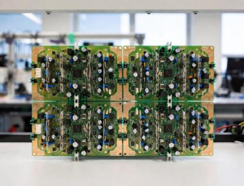
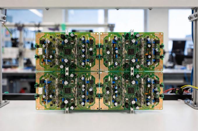
What Is an RF PCB?
RF-printed circuit card are just one of the sorts of high-frequency printed circuit board. RF PCB is a
high-frequency board made using radio frequency innovation. RF printed circuit board is a very
high-speed circuit with a frequency of 100mhz and above, normally in between 500mhz-2ghz. Over 2ghz is a
microwave PCB.
As a result, the difference in between RF PCB and microwave circuit board lies in frequency. There are
likewise some differences in circuit board style.
Radio frequency circuits can be designed using lumped parameter components or mixed parameter
components.
Considering that the dimension of microwave circuits is almost the same as their wavelength, they need
to be developed utilizing distributed parameter components.
Features of RF-Printed Circuit Boards
The production of RF-printed circuit boards is so rigorous and needs extra advanced mechanical
equipment, such as plasma etching equipment, laser direct imaging (LDI), and so on. With the assistance
of this precision equipment and RF modern technology, RF printed circuit board have the following
features:
1) Strong Temperature Level Control Ability
The thermal conductivity of RF-printed printed circuit board is lower than that of average printed
circuit boards constructed from FR-4 material. It means they can run under high-temperature problems for
a long period of time without being damaged.
2) High Frequency
Compared with various other circuit boards, their electromagnetic wave regularity is greater, so the
signal transmission distance is much longer and can cover a big area, allowing cordless interaction
devices to transfer details in time.
3) Solid Security
The RF PCB substrate product is polytetrafluoroethylene (PTFE), which has a reduced coefficient of
thermal expansion (CTE) than standard FR4. Consequently, the RF board is a lot more steady in
high-temperature atmospheres.
When developing a PCB, you can mix PTFE materials and FR4 to construct a PCB stack up and minimize the
board location. Since FR4 is more affordable, it can additionally lower manufacturing costs.
What Materials do You Need for RF Circuit board?
The material needs to be picked based on factors such as dielectric continuous (DK), dissipation factor
(DF), coefficient of thermal expansion (CTE), manufacturability, passive intermodulation (PIM), price
considerations, etc. Different products have various application scenarios, so when creating, it is
needed to think about and review the task in numerous aspects to meet the design performance
requirements.
1) Polytetrafluoroethylene (PTFE)
PTFE is preferred in RF layout because of its low thermal growth coefficient, high dielectric
consistent, and stable performance, such as Teflon and Rogers products.
2) FR-4
FR- mean fire retardant. FR -4 is just one of one of the most common PCB materials. Its price is
relatively low compared to PTFE. It is normally appropriate for digital gadgets. However, in
higher-frequency RF applications, the high thermal expansion coefficient of FR-4 will be restricted.
3) RO4000 Collection
It is a particular collection of PTFE or glass fiber composite products. Reduced Dk and reduced loss,
suitable for high-frequency circuit style, decrease passive intermodulation (PIM) efficiency and give
better security.
4) RO3000 Series
Similar to RO4000, the RO3000 collection is additionally a PTFE-based product but has different
dielectric constants and other homes, appropriate for various RF styles. Models consist of: RO3003,
RO3006, RO3010, RO3035 high frequency laminates.
5) Aluminum-Based Printed Circuit Board
Appropriate for high-power radio frequency areas, this circuit board generally uses an aluminum
substratum to enhance warmth dissipation and electric homes.
6) Metallized Ceramics
It is made use of in some extremely high-frequency and microwave-frequency tools. The metalized ceramic
PCBs can supply reduced dielectric loss and superb security.
Application of RF Circuit Boards
1) Communications
Radiofrequency technology is substantial in cordless communications, such as mobile interactions,
satellite interactions, wireless broadcasting, radar, and other fields.
2) Electronic Radio Frequency Equipment Field
Radiofrequency technology plays an essential duty in electronic gadgets, such as televisions, radio
terminals, microwave, and other areas.
3) Medical and Life Sciences
Radiofrequency modern technology is widely used in clinical and life science areas, such as clinical
imaging, medicine development, and biological testing.
4) Electronic Games
Radiofrequency modern technology is commonly utilized in electronic games, such as wireless microphones,
cordless controllers, near-field communications, and so on.
5) Aerospace
Radiofrequency innovation is likewise essential in artificial satellites and room exploration, such as
orbit control, satellite interactions, and so on.
To sum up, radio frequency modern technology is extensively utilized in different industrial and
clinical areas and plays an important role.
What Factors Should Be Taken Into Consideration in RF PCB Design?
There are many elements to consider when making a printed circuit board, such as criterion setups,
producing expenses, manufacturability, etc. Amongst them, parameter setups are crucial because they
impact the sensible efficiency of the circuit board.
In RF board design, you can accomplish the most effective efficiency of the circuit card.
1) Impedance Matching
It is important to decrease circuit signal loss, and proper impedance matching can make certain power
transmission effectiveness between elements. This procedure primarily considers the line size, spacing,
substrate material, and transmitting setup.
2) Cable Routing Design
Signal transmission is propagated via the traces, so the layout of the traces is significant. It is
easily affected. It is generally best to have coplanar and short traces to decrease losses and enhance
performance.
3) Through Hole Utilization
It might create parasitical capacitance (unplanned capacitance), which can trigger signal distortion.
For that reason, in the design, vias must be minimized as high as feasible, the hole dimension need to
be kept consistent, and certain vias ought to be made certain for the pins or pads.
4) Ground Planes and Vias
5) Power Supply Decoupling
RF circuit boards require noise reduction to be efficient, and power supply decoupling is one method to
eliminate sound. Picking decoupling capacitors can get rid of all power supply-introduced sound, so it
is critical to put the capacitors meticulously.
• RF components and capacitors should be placed on the exact same side.
• Each capacitor have to have a ground using.
• The capacitor with the lowest power is positioned near the power supply and is prepared from huge to
tiny.
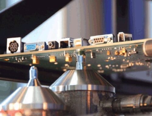
RF PCB Manufacturing (Unique Processes and Technologies)
The production procedure of RF circuit boards is rather different from that of typical printed circuit
board. In order to preserve the performance and stability of high-frequency circuits, there are some key
production processes.
1) Product Choice
As a result of its high-frequency performance, it is vital to pick the material. Common materials
include polytetrafluoroethylene (such as Teflon and RO4000 collection materials ).
2) Imaging, lamination, Etching
RF circuit boards have high needs for accuracy, so laser imaging machines are made use of in the imaging
phase, and plasma etching equipments are used throughout etching. It makes certain the circuit accuracy
fulfills the design requirements.
3) Control Board Thickness
Board density influences the electrical stability in between circuits, so it must correspond during PCB
production flow.
RF Circuit Testing
1) Impedance Examination
Impedance matching testing must be done during the circuit card production. It impacts signal loss. The
examination makes sure that the circuit insusceptibility follows the designed impedance. Typically, the
time domain reflection test (TDR) is used.
2) Functional Loss Test
Check the loss features of RF PCB within the designed power array to make sure that the signal
transmission top quality is not impacted by too much loss. Typical test techniques consist of:
• Frequency conversion method
• Transmission Line Method
• Heat balance method
• DC Power Measurement Method
3) Environmental Versatility Examination
Evaluate the circuit board under different temperature level and humidity problems to assess its
stability and integrity in various environments
Future Trends
With the rapid growth of the Net of Points, 5G communications, clever homes, and various other fields,
the demand for the RF PCB market is showing a rapid development fad, promoting further technology and
market competition in RF modern technology.

