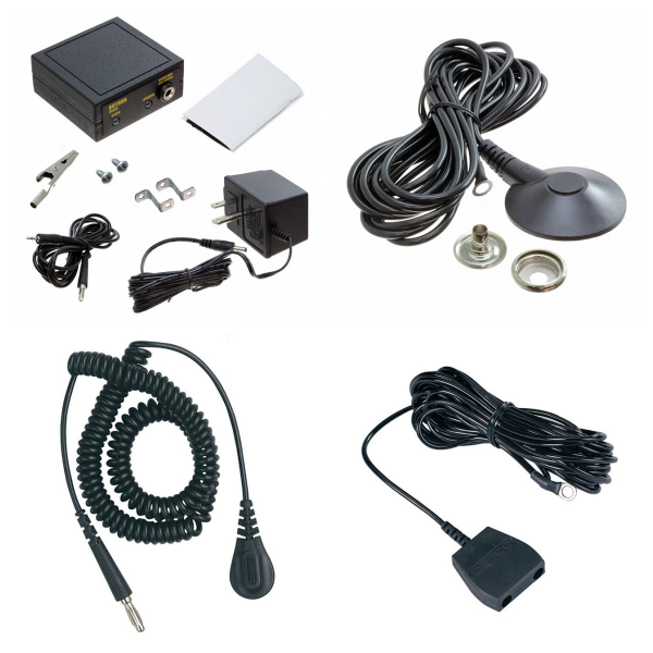
<h1> Anti-Static, ESD, Clean Room Products </h1> <h2> 1. Protective clothing and personal protective equipment </h2> <p> Antistatic work clothes: Made of washable polyester mesh material, with various colors (such as white, blue, pink, etc.), suitable for clean room environments such as microelectronics and optoelectronics, and ESD certified to ensure electrostatic protection performance. </p> <p> Antistatic shawl cap: Reduce the impact of static electricity generated by human activities on sensitive components, need to be cleaned 1-2 times a week, and regularly check the wear and tear, suitable for electronic manufacturing and microelectronics industries. </p> <h2> 2. Antistatic materials and packaging </h2> <p> Antistatic ixpe foam: Made of polyethylene as the base material, made by radiation cross-linking foaming process, the surface resistance is stable at 10⁶–10⁹Ω, the antistatic performance is not affected by environmental humidity, and it is an ideal packaging material for integrated circuits and optoelectronic devices. </p> <p> Antistatic PE/PO film: The electrostatic protection function is achieved through a three-layer co-extrusion process, used to protect the surface of precision electronic devices. </p> <h2> 3. Turnover and transportation equipment </h2> <p> ESD turnover boxes/trays/carts: made of acid-resistant, alkali-resistant and oil-resistant materials, suitable for the transportation and storage of electronic components, and can be used in clean room environments. </p> <h2> 4. Clean room auxiliary equipment </h2> <p> Work area equipment: including anti-static chairs, anti-static table mats, anti-static door curtains, etc., which reduce the risk of static electricity accumulation through conductive materials. </p> <p> Personal protection tools: such as anti-static gloves, work shoes, wrist straps, etc., which can be used with clothing to enhance the overall protection effect. </p> <p> Other tools: anti-static shielding bags, component boxes, sticky mats, etc., used for component storage and environmental cleaning. </p> <h2> 5. Ground and infrastructure protection </h2> <p> Anti-static epoxy resin floor: The anti-static function of the ground is achieved through the conductive coating, which is commonly found in electronic manufacturing workshops and laboratories. </p> <p> The above products effectively control the generation and accumulation of static electricity through material characteristics, functional design and systematic application, and ensure the production safety and efficiency of sensitive environments such as precision electronic manufacturing and microelectronics. </p>
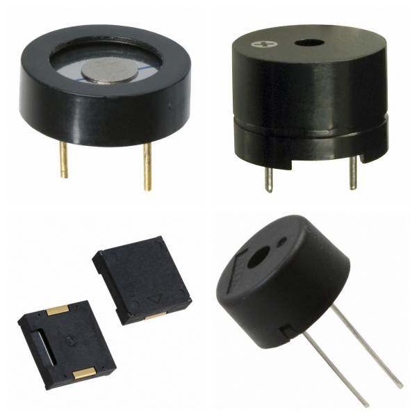
<h1> Audio Products </h1> <h2> 1. What are the Main Types of Audio Products? </h2> <h3> 1) Speaker </h3> <p> <strong>Function</strong>: Converts audio electrical signals into sound energy output, and is the core component of the audio system. </p> <p> <strong>Technical features</strong>: </p> <p> Uses a pure piston drive design, combined with aluminum and damping materials to reduce distortion. </p> <p> Sensitivity, frequency response, and directional characteristics directly affect the sound quality. </p> <h3> 2)Microphone </h3> <p> <strong>Types</strong>: Including capacitive (ECM, MEMS), dynamic, piezoelectric, etc. </p> <p> <strong>Application</strong>: Voice interaction, active noise reduction and recording scenarios, MEMS microphones have become the first choice for consumer devices due to their high consistency. </p> <p> <strong>Audio connector</strong> </p> <p> <strong>Structure</strong>: Divided into balanced, separate, and non-separate circuit designs, affecting anti-interference ability and signal transmission quality. </p> <p> <strong>Process requirements</strong>: The appearance must be free of burrs and leaks to ensure stability and durability. </p> <h3> 3)Dynamic Unit </h3> <p> <strong>Innovative technology</strong>: For example, the runway-type dynamic unit improves acoustic performance by optimizing the diaphragm material, which is suitable for professional microphones and micro speakers. </p> <h2> 2. What are the Key Performance Parameters of Audio Products? </h2> <p> <strong>Nominal power and impedance</strong>: The speaker needs to match the rated power (such as 0.1W~200W) and impedance (4Ω~32Ω) to ensure compatibility. </p> <p> <strong>Frequency response</strong>: Determines the audio coverage range, and high-end speakers can reach 23Hz~52kHz. </p> <p> <strong>Distortion</strong>: Including harmonic distortion and intermodulation distortion, which directly affects the sound quality restoration. </p> <h2> 3. What are Audio Products Used for? </h2> <p> <strong>Consumer electronics</strong>: Smart speakers, headphones, etc. rely on micro speakers and MEMS microphones to achieve high-fidelity interaction. </p> <p> <strong>Professional audio</strong>: Floor-standing speaker systems with multi-frequency design meet the high dynamic requirements of theaters and recording studios. </p> <p> <strong>Industrial equipment</strong>: Durable piezoelectric ceramics and buzzers are used in scenarios such as alarms and status prompts. </p> <h2> 4. What are the Technology Development Trends of Audio Products? </h2> <p> <strong>Material innovation</strong>: Such as the application of laminated diaphragms and aerospace-grade aluminum materials to improve driver efficiency and durability. </p> <p> <strong>Integrated design</strong>: The acoustic module integrates the microphone, speaker, and processing circuit to simplify the internal structure of the device. </p> <h2> 5. Best brands for Audio Products </h2> <p> Bose </p> <p> Sony </p> <p> JBL </p> <p> Yamaha </p> <p> Pioneer </p>
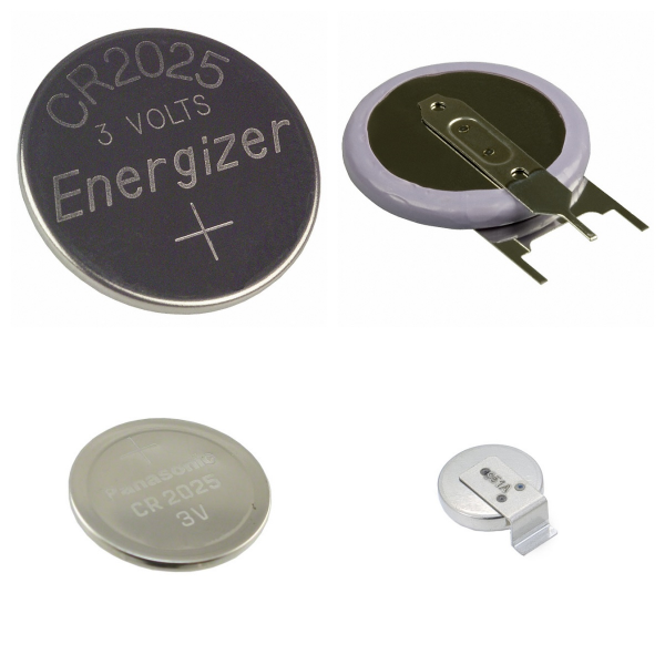
<h1> Battery Products </h1> <h2> 1.What are the Core Components of Battery Products? </h2> <p> <strong>Cell</strong>: As the basic unit of the battery, it is composed of a positive electrode, a negative electrode, a separator and an electrolyte, providing a voltage output of 3V-4V. The materials include lithium-ion, nickel metal hydride or lead acid, etc. </p> <p> <strong>Batteries</strong>: It is composed of multiple cells connected in series/parallel to increase voltage or capacity, such as 12V modules or high-capacity combinations. </p> <p> <strong>Battery Pack</strong>: It is integrated by a battery pack and equipped with a battery management system (BMS) to form a product that can be directly applied, such as an electric vehicle lithium battery pack. </p> <h2> 2. What are the Packaging Types of Battery Products? </h2> <p> <strong>Hardshell packaging</strong>: It uses steel/aluminum materials and is divided into cylindrical (high production efficiency) and square (compact structure). </p> <p> <strong>Soft package packaging</strong>: It uses aluminum-plastic film, which has the advantages of lightweight and high energy density, but the degree of automation is low. </p> <p> <strong>Supercapacitor</strong>: It is between batteries and traditional capacitors, supports fast charging and discharging, and has a long cycle life, and is suitable for high-power scenarios. </p> <h2> 3. What are the Technical Features of Battery Products? </h2> <p> <strong>Patented technology</strong>: such as heating connector design, optimizing thermal management of battery box and external environment. </p> <p> <strong>Material innovatio</strong><strong>n</strong>: Graphene electrodes improve conductivity, and ionic liquid electrolytes enhance stability. </p> <p> <strong>Process differences</strong>: The cylindrical winding process is highly efficient, and the square stacking process is suitable for soft-pack batteries. </p> <h2> 4. What are Battery Products Used for? </h2> <p> <strong>Consumer electronics</strong>: mobile power supplies, smart devices, etc.. </p> <p> <strong>Industry and transportation</strong>: electric vehicle power batteries, energy storage systems and outdoor equipment (such as garden tools). </p> <p> <strong>Emerging fields</strong>: high-power demand scenarios such as grid regulation and robots. </p> <h2> 5. The Industry standards and compliance requirements of Battery Products </h2> <p> <strong>Safety certification</strong>: Cross-border e-commerce needs to provide IEC/EN62133 or UL2054/UL1642 certification and temperature test reports. </p> <p> <strong>MSDS file</strong>: Lithium batteries must include component data, hazardous materials classification and emergency disposal plans to ensure safe transportation and use. </p> <p> International Standards: Following the GHS standards, each country should issue SDS documents (such as EU REACH, China GB/T 16483). </p> <h2> 6.The Challenges and Development Directions of Battery Products </h2> <p> <strong>Energy density improvement</strong>: Supercapacitors need to break through the bottleneck of low energy density. </p> <p> <strong>Cost and consistency</strong>: Soft-pack batteries rely on imported aluminum-plastic films, and production consistency needs to be improved. </p> <p> <strong>Environmental protection needs</strong>: Promote the research and development of green technologies such as cobalt-free batteries and solid electrolytes. </p> <h2> 7. Battery Products FAQs </h2> <h3> 1) Whether the Temperature Affects the Life of the Battery Products? </h3> <p> Yes. High or low-temperature environments may affect battery performance. It is recommended to avoid charging or discharging at extreme temperatures. </p> <p> Some batteries have low/high-temperature protection functions: </p> <p> <strong>When charging</strong>: Charging stops automatically when the temperature is below 0°C or above 55°C. </p> <p> <strong>When discharging</strong>: Discharging stops when the temperature is below –10°C or above 55°C. </p> <h3> 2) What are the Precautions When Charging with Battery Products? </h3> <p> Using the original charger can optimize charging efficiency and extend battery life. </p> <p> When using a new battery for the first time, it is recommended to fully charge and discharge to activate battery performance (applicable to some models). </p> <h3> 3) How to Maintain the Battery Products? </h3> <p> Regularly cleaning the internal blockages of the device (such as vacuum cleaner filters) can improve battery efficiency. </p> <p> When storing the battery for a long time, keep the power at 30%-50% to slow down aging. </p> <h3> 4) How to Troubleshoot Battery Products? </h3> <p> If the battery is abnormally hot or cannot be charged, it is recommended to contact the official after-sales service for inspection. </p> <p> Some batteries support remote positioning function (such as mobile phone batteries), which is convenient for tracking when the device is lost. </p>
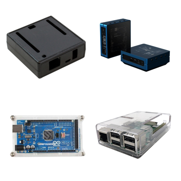
<h1> Boxes, Enclosures, Racks </h1> <p> "Boxes, Enclosures, Racks" are key components used for physical protection, electromagnetic compatibility management and system integration in the field of electronic equipment. </p> <h2> 1. What are the Core Functions of Boxes, Enclosures and Racks? </h2> <p> Physical Protection: Electronic devices should have shell protection to guard against environmental interference from dust, moisture, vibration, and other sources. </p> <p> Electromagnetic Compatibility (EMC): Utilize high attenuation materials and shielding structure design to minimize electromagnetic interference (EMI) produced by internal high-speed electronic equipment and guarantee device compatibility. </p> <p> Modular Integration: Support standardized installation and expansion of multi-level equipment (such as power supply, control module, etc.) to improve system maintenance efficiency </p> <h2> 2. What are the Design Points of Boxes, Enclosures and Racks? </h2> <p> Material Selection: Use metal or conductive composite materials to enhance electromagnetic shielding effectiveness, and optimize equipment temperature control through heat dissipation design </p> <p> Structural Optimization: Including sealed interfaces, grounding design, etc., to balance protection level and equipment maintainability </p> <p> Compatibility Adaptation: The layout needs to be adjusted according to the type of internal components (such as active/passive components) to avoid signal interference </p> <h2> 3. What are Boxes, Enclosures and Racks Used for? </h2> <p> Industrial Equipment: used for protection in complex environments such as automation control systems and power electronic devices. </p> <p> Communication Base Stations: When integrating high-frequency signal processing modules, shielded cabinets are required to reduce radio frequency interference. </p> <p> Laboratory Testing: Provide a stable electromagnetic environment for precision instruments to ensure measurement accuracy. </p> <h2> 4.What are the Core Components of Boxes, Enclosures and Racks? </h2> <p> Electronic components in the chassis/rack usually include: </p> <p> Active components: such as integrated circuits and transistors, are used for signal amplification or control. </p> <p> Passive components: such as resistors and capacitors, undertake energy regulation or filtering functions. </p> <p> Composite components: Class C devices such as sensors and relays, which realize modular integration of specific functions. </p> <p> Through the above design, the products in this column meet the needs of modern electronic systems for compactness, high efficiency and environmental adaptability while ensuring equipment reliability. </p>
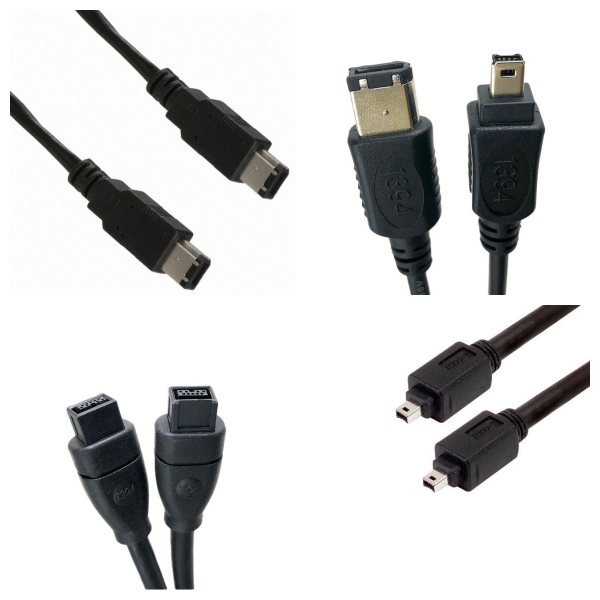
<h1> Cable Assemblies </h1> <p> Cable Assemblies play a key role in efficient connection and signal integrity in electronic systems. </p> <h2> 1. Cable Assemblies Overview </h2> <p> Cable Assemblies (cable assemblies) are pre-assembled integrated wiring harnesses composed of connectors, wires and insulation layers, which are used to achieve signal transmission or power connection between electronic devices. </p> <p> <strong>Its core functions include</strong>: ensuring stable transmission of high-frequency/high-speed signals (such as RF coaxial cable assemblies), adapting to different interface standards (such as QSFP+ interfaces), and simplifying the complexity of internal wiring of equipment. </p> <h2> 2. What are the Core Components of Cable Assemblies? </h2> <p> <strong>Connectors</strong>: Such as RF coaxial connectors, QSFP+ interfaces, etc., are responsible for docking with device ports. </p> <p> <strong>Wire and insulation layer</strong>: The combination of conductor material (such as copper core) and insulation layer (such as PVC or Teflon) determines electrical performance and environmental resistance. </p> <p> <strong>Protective structure</strong>: Some components need to add shielding layers or protective sleeves to resist electromagnetic interference or mechanical damage. </p> <h2> 3. What are the Technical Process of Cable Assemblies? </h2> <p> <strong>1) Manufacturing Process</strong>: </p> <p> <strong>Crimp</strong>: The terminal and the conductor are fixed by a crimping tool, and the contact resistance between the conductor and the terminal must meet the standard. </p> <p> <strong>Insulation Displacement Connection (IDC)</strong>: The terminal blade is used to pierce the insulation layer of the wire to directly contact the conductor, which is suitable for flat cable scenarios. </p> <p> <strong>Solder</strong>: Including wave soldering, reflow soldering, etc., used for precision connection in high-density or high-frequency scenarios. </p> <p> <strong>2) Quality Inspection</strong>: Tensile test, appearance inspection (such as conductor length, terminal deformation) and electrical performance test (such as standing wave ratio) are required. </p> <h2> 4. What are Cable Assemblies Used for? </h2> <p> <strong>Communication Equipment</strong>: RF coaxial cable assemblies are widely used in high-frequency signal transmission scenarios such as base stations and satellite communications. </p> <p> <strong>Data Center</strong>: High-speed cables (such as 40G QSFP+ assemblies) are used for high-speed interconnection between servers and switches. </p> <p> <strong>Industrial Equipment</strong>: Customized cable assemblies meet the requirements of high-temperature resistance and vibration resistance in complex environments. </p> <h2> 5. Which Brands Have the Best Cable Assemblies? </h2> <p> <strong>Amphenol</strong>: Provides QSFP+ cable assemblies, supporting 40G network transmission. </p> <p> <strong>EAM CABLE ASSEMBLIES</strong>: Mainly engaged in multi-category connectors and wiring harness solutions, adapted to industrial and consumer electronics fields. </p>
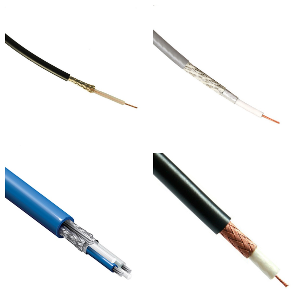
<h1> Cables, Wires </h1> <h2> 1. What are Cables and Wires? </h2> <p> Cables: Made up of multiple individually insulated wires, the outer layer usually contains a protective layer, is used for power transmission, communication or signal transmission, and has a multi-conductor transmission function. </p> <p> Wires: A single conductor (such as copper or silver), covered with an insulating material (such as plastic, rubber) on the outer layer, mainly used for low-power power or signal transmission. </p> <h2> 2. What is the difference between Cables and Wires? </h2> <p> Structural Complexity: Cables are made up of multiple wires bundled with an additional protective layer, while wires are usually single conductors. </p> <p> Application Scenarios: Wires are suitable for simple circuit connections; cables are mostly used in high-traffic scenarios, such as industrial control, fiber optic communications, etc.. </p> <h2> 3. What are the Key Parameters of Cables and Wires? </h2> <p> Bandwidth: Transmission capacity, measured by bit rate (bit rate, the number of bits transmitted per second). </p> <p> Latency: The time it takes for data to travel from the sender to the receiver. </p> <h2> 4. What are the Types of Cables and Wires? </h2> <p> 1)Classification By Material: including PVC, rubber, halogen-free cables, etc. </p> <p> 2)Classification By Function: </p> <p> Flame-retardant Cable: can limit the spread of fire, suitable for scenarios with high safety requirements. </p> <p> Fiber-optic Cable: used for high-speed data transmission. </p> <h2> 5. What are Cables and Wires Used for? </h2> <p> Industry: factory automation, solar equipment. Communication: fiber-optic communication, telecommunication network. </p> <p> Consumer Electronics: medical equipment, automotive electronics, IT infrastructure. </p> <h2> 6. What are the Standards and certification of Cables and Wires? </h2> <p> Must comply with international cable standards such as UL, Japanese standard/Taiwan standard. </p> <h2> 7. Cables and Wires FAQs </h2> <h3> 1) What are the Main Types of Cables and Wires? </h3> <p> Power/Signal Transmission Cables: including power cables, and data cables (such as Cat5e, Cat6, Cat7). </p> <p> Special Cables: such as AV cables, optical fibers, and military cables (for defense equipment). </p> <p> Industrial Cables: such as cable sleeves, and cables for shrink wrap sealers. </p> <h3> 2) How to Choose the Right Cable? </h3> <p> Network Performance Requirements: Cat5e is suitable for Gigabit Ethernet, and Cat6/Cat7 supports higher bandwidth and anti-interference. </p> <p> Environmental Adaptability: The power cord needs to match the power capacity and connector specifications of the device; military scenarios require high-durability materials. </p> <p> Cost and Quality: Copper-clad aluminum (CCA) conductors are cost-effective, but pure copper has better conductivity. </p> <h3> 3) What are the Installation Precautions for Cables and Wires? </h3> <p> Make sure the power cord connector is compatible with the device interface to avoid power overload. </p> <p> Use heat shrink tubing or professional sealers to improve cable insulation and protection levels. </p>
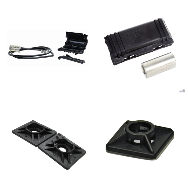
<h1> Cables, Wires - Management </h1> <h2> 1. What is the Management of Cables and Wires? </h2> <p> This column focuses on the physical management and signal integrity maintenance of cables and wires in electronic systems, covering wiring planning, connection reliability optimization, identification classification and daily maintenance, aiming to reduce the risk of signal interference and improve the stability of equipment operation. </p> <h2> 2. What are the Core Management Methods of Cables and Wires? </h2> <h3> 1)Physical Management </h3> <p> Wiring Tools: Use tools such as trunking, cable ties and cable clips to organize the cable route to avoid entanglement or excessive bending. </p> <p> Modular Design: The terminal module can be used to quickly connect and disassemble the cable, support multi-channel access and electrical isolation, and is suitable for complex industrial environments. </p> <h3> 2)Identification and Marking </h3> <p> Use color-coded labels, heat shrink tubing or self-adhesive identification stickers to distinguish cables with different functions, which is convenient for quick identification and troubleshooting. </p> <p> Special scenarios (such as medical equipment) require the use of flame-retardant memory identification sleeves to ensure the durability of identification in high-temperature or high-pressure environments. </p> <h3> 3)Maintenance measures </h3> <p> Regularly check the wear of the cable insulation layer to avoid short circuits due to aging. </p> <p> For high-frequency signal scenarios (such as ECG equipment), the wire layout needs to be optimized to reduce electromagnetic interference. </p> <h2> 3. Why is the Management of Cables and Wires very Important? </h2> <p> Industrial control: Manage multiple signal lines through terminal modules to ensure electrical isolation and seismic resistance. </p> <p> Medical equipment: ECG wires need to be made of flexible materials and equipped with special organizing tools to balance patient safety and ease of operation. </p> <p> Consumer electronics: Hidden cable ducts and mini cable ties are often used in home and office scenarios to improve the appearance of equipment. </p> <h2> 4. What are the Technology Development Trends of the Management of Cables and Wires? </h2> <p> Current management solutions are moving towards intelligence and high-density integration, such as introducing sensors to monitor cable status or developing miniaturized tags to adapt to compact electronic devices. </p>
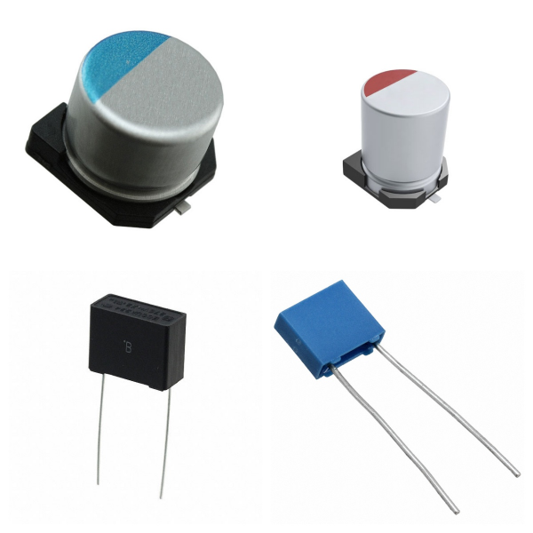
<h1> Capacitors </h1> <p> Capacitors play a vital role in electronic circuits. Reasonable selection and use are the keys to ensuring circuit performance. </p> <h2> 1. Capacitors Overview </h2> <p> A capacitor is a passive electronic component consisting of two conductors (plates) close to each other and a non-conductive insulating medium (dielectric) in the middle, used to store charge and electrical energy. Its core function is to achieve temporary storage and release of energy through the charging and discharging process. </p> <p> The calculation formula of capacitance (unit: Farad, F) is: </p> <p> C=εS/4πkd </p> <p> Where ε is the dielectric constant, S is the plate area, and d is the plate spacing. </p> <h2> 2. What are the Core parameters of Capacitors? </h2> <p> <strong>Capacitance</strong>: There is a tolerance between the nominal value and the actual value, and the accuracy is usually 5%~25%. </p> <p> <strong>Rated voltage</strong>: The maximum voltage limit for the normal operation of the capacitor. </p> <p> <strong>Dissipation factor</strong>: Reflects the energy loss of the dielectric material and the equivalent series resistance (ESR). </p> <p> <strong>Temperature coefficient</strong>: The effect of temperature change on capacitance, expressed in ppm (parts per million). </p> <p> <strong>Leakage current</strong>: Determined by dielectric insulation performance, affecting long-term stability. </p> <h2> 3. What are the Types of Capacitors? </h2> <h3> 1)Differentiation by polarity: </h3> <p> <strong>Non-polar capacitors</strong>: Such as ceramic capacitors and film capacitors, which can be installed in any direction, but have a small capacity. </p> <p> <strong>Polar capacitors</strong>: Such as electrolytic capacitors (aluminum electrolytic, tantalum capacitors), which have large capacity but must strictly distinguish between positive and negative poles. </p> <h3> 2)Differentiation by structure: </h3> <p> <strong>Fixed capacitors</strong>: The capacitance is immutable. </p> <p> <strong>Variable capacitors</strong>: Change the plate spacing or area through mechanical adjustment. </p> <h2> 4.What are the Functions and Applications of Capacitors in Circuits? </h2> <p> <strong>Power supply filtering</strong>: Smooth voltage fluctuations and suppress high-frequency noise. </p> <p> <strong>Signal coupling/decoupling</strong>: Block DC components and transmit AC signals. </p> <p> <strong>Energy storage and tuning</strong>: Used in resonant circuits, energy buffering and other scenarios. </p> <p> <strong>Timing control</strong>: Cooperate with resistors to realize RC charging and discharging delay function. </p> <h2> 5. The Selection and Use Precautions of Capacitors </h2> <p> <strong>1)Voltage margin</strong>: The rated voltage must be higher than the maximum operating voltage of the circuit. </p> <p> <strong>2)Temperature adaptability</strong>: A model with a stable temperature coefficient must be selected in a high-temperature environment. </p> <p> <strong>3)Polarity judgment</strong>: <span style="font-size: 16px;">The short pin or the shell mark "-" is the negative pole of the electrolytic capacitor.</span><span style="font-size: 16px;">The dark end of the tantalum capacitor is the negative pole.</span><span style="font-size: 16px;"></span> </p> <p> <strong>4) Installation form</strong>: The direct plug-in type is suitable for manual welding, and the SMD type is suitable for high-density PCB layout. </p> <h2> 6. Which Brands Have the Best Capacitors? </h2> <p> CHEMICON </p> <p> NICHICON </p> <p> YAGEO </p> <p> TDK </p> <p> AISHI </p> <h2> 7. Capacitors FAQs </h2> <h3> (1) How to Use Tantalum Capacitors Safely? </h3> <p> Avoid overvoltage or reverse voltage, otherwise, it may cause overheating or even short circuit; </p> <p> Some models support short-term over-temperature applications, but the derating guidelines provided by the manufacturer must be followed. </p> <h3> (2) How to Choose Capacitors in Circuit Design? </h3> <p> Low ESR capacitors (such as conductive polymer capacitors) should be preferred in power supply filtering scenarios to improve efficiency; </p> <p> High-frequency circuits need to consider the impact of ESL, and it is recommended to use multi-layer ceramic capacitors or low-inductance packages. </p> <h3> (3) How to Maintain Capacitors? </h3> <p> Tantalum capacitors usually have a long shelf life in unopened original packaging, but humid environments should be avoided to prevent oxidation. </p> <h3> (4) How to Choose the Capacitance Combination of Bypass Capacitors? </h3> <p> In high-frequency power supply design, it is usually recommended to use multiple capacitance values in parallel (such as 0.01μF and smaller capacitance capacitors) to cover the noise suppression requirements of different frequencies and add large-capacity capacitors (such as 10μF) at the power supply entrance to stabilize the power supply. </p> <h3> (5) What are the Advantages of Temperature-compensated Ceramic Capacitors? </h3> <p> Temperature-compensated ceramic capacitors (such as C0G material) have almost no capacitance change over a wide temperature range and are not affected by DC bias, making them suitable for high-precision scenarios such as high-frequency filtering and oscillation circuits. </p>
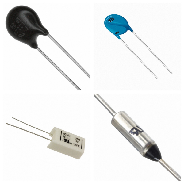
<h1> Circuit Protection </h1> <h2> 1. What are the Core functions of Circuit Protection? </h2> <p> Circuit protection is a protection mechanism for electronic devices or systems against abnormal electrical conditions, mainly including the following functions: </p> <p> Overvoltage protection: Prevent device breakdown caused by voltage transients (such as surges, and electrostatic discharge). Common protection components include varistors (MOVs) and transient suppressor diodes (TVSs). </p> <p> Overcurrent protection: Prevent thermal damage to the circuit caused by current overload by fusing or current limiting. Typical devices include self-resettable fuses (PPTCs) and traditional fuses. </p> <p> Temperature protection: Cut off the circuit by fusing or temperature-sensitive switches to prevent overheating, such as low-temperature alloy over-temperature protection components. </p> <p> Compound protection: Integrated temperature, current, and voltage multi-monitoring protection solutions (such as TFR), widely used in high-safety demand scenarios such as lithium batteries. </p> <h2> 2. What are the Main components and principles of Circuit Protection? </h2> <p> MOV (metal oxide varistor) </p> <p> Absorbs transient overvoltage energy through nonlinear resistance characteristics, suitable for power line surge protection. </p> <p> TVS (Transient Suppression Diode) </p> <p> Quick response (nanosecond level) voltage spikes, used for ESD protection of precision circuits. </p> <p> GDT (Gas Discharge Tube) </p> <p> Uses the principle of gas ionization to discharge high-energy surges, with a current resistance of 20kA, suitable for lightning protection of communication equipment. </p> <p> PPTC (Self-Resettable Fuse) </p> <p> Overcurrent protection is achieved based on temperature-resistance characteristics, and can automatically recover after the fault is removed. </p> <p> TFR (Overtemperature and Overcurrent Protection Device) </p> <p> Simultaneously monitors temperature and current anomalies, and is suitable for complex scenarios such as motors and 3C products. </p> <h2> 3. Where is Circuit Protection Used? </h2> <p> Consumer Electronics: High-speed transmission devices such as smartphones and USB interfaces rely on TVS/MOV to prevent static electricity and surge shocks. </p> <p> Automotive Electronics: The on-board power system needs to deal with the startup peak voltage, and MOV and polymer capacitors work together to ensure stability. </p> <p> Industrial Equipment: The power system uses a combination of GDT and MOV to resist lightning strikes and grid fluctuations. </p> <p> Communication base station: Ceramic gas discharge tubes (GDT) and semiconductor discharge tubes are preferred in lightning protection design. </p> <h2> 4. Technology development trend of Circuit Protection </h2> <p> High integration: A single component integrates multiple protection functions (such as TFR) to simplify the complexity of circuit design. </p> <p> Intelligent response: Combine sensors and microcontrollers to achieve dynamic threshold adjustment and improve protection accuracy. </p> <p> High-temperature material innovation: Develop high-temperature resistant alloys and polymer materials to expand the scope of application in extreme environments. </p>
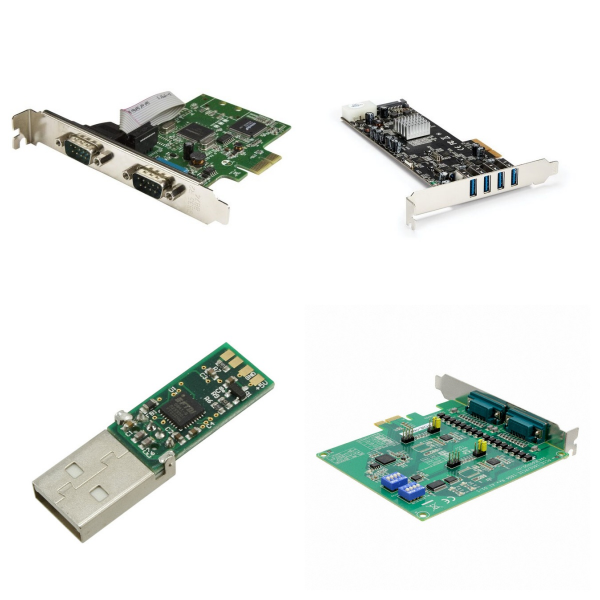
<h1> Computer Equipment </h1> <p> The essence of computer equipment is the highly integrated application of electronic components. Its performance improvement directly depends on the progress of semiconductor technology, packaging technology, and the coordinated optimization of passive components and active devices. </p> <h2> 1. What are the Core Components of Computer Equipment? </h2> <p> Integrated Circuit (IC) </p> <p> As the "brain" of computer equipment, integrated circuits integrate transistors, resistors, capacitors and other components on semiconductor wafers through microelectronics technology to achieve functions such as logic operations and data storage. </p> <p> Semiconductor Devices </p> <p> They include CPU (central processing unit), GPU (graphics processing unit), memory chips (such as DRAM, NAND flash memory), etc. These devices are based on silicon-based semiconductor materials and realize signal processing and information storage by controlling current. </p> <p> Passive Components </p> <p> Such as resistors, capacitors, inductors, etc. are used for current limiting, filtering, voltage stabilization and other functions in the circuit to ensure the stability of computer equipment operation. </p> <h2> 2. Typical Equipment and Functions </h2> <p> Computer host </p> <p> It consists of a motherboard, power module, storage device (hard disk/solid-state drive), etc., and relies on integrated circuits and semiconductor devices to complete data processing, storage and transmission. </p> <p> Peripherals and interface modules </p> <p> Such as display driver circuits, USB interface controllers, network communication modules, etc., involve the coordinated work of discrete devices such as field effect transistors (FETs) and thyristors. </p> <p> Industrial control equipment </p> <p> Including CNC systems, automated robots, etc., which require high-precision sensors, and power semiconductors (such as IGBTs), etc. to implement complex control logic. </p> <h2> 3. Production and Manufacturing Technology of Computer Equipment </h2> <p> The production of computer equipment depends on special equipment for the electronics industry, such as: </p> <p> Integrated circuit manufacturing equipment: lithography machines, etching machines, ion implanters, etc. </p> <p> Assembly and testing equipment: surface mount machines (SMT), automatic welding robots, functional testers, etc. </p>
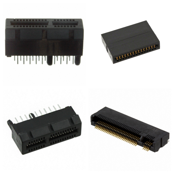
<h1> Connectors, Interconnects </h1> <h2> 1. Connectors Overview </h2> <p> Connectors are key components for realizing the physical connection of circuits in electronic systems. They establish transmission channels for electrical, optical or microwave signals between two active devices or subsystems through detachable interfaces. Its core functions include: </p> <p> Electrical signal transmission: transmitting current, voltage, data signals, etc., and ensuring signal stability and integrity; </p> <p> Modular design: supporting rapid assembly, repair and upgrading of equipment, reducing production and maintenance costs; </p> <p> Environmental adaptability: providing waterproof, dustproof, anti-vibration and other protection functions, adapting to complex working environments. </p> <h2> 2. What are the Core Components of Connectors? </h2> <p> Connectors are usually composed of the following components: </p> <p> Contact parts: metal conductors (such as copper alloys plated with gold), responsible for current or signal transmission; </p> <p> Insulator: plastic/ceramic material, isolating different contacts to prevent short circuits; </p> <p> Shell: metal or engineering plastic, providing mechanical support and protection; </p> <p> Locking mechanism: buckle, thread and other designs to ensure connection stability. </p> <h2> 3. What are the Types of Connectors? </h2> <p> According to the transmission medium and application scenarios, it is mainly divided into the following categories: </p> <p> Electrical connector: such as D-SUB, USB, HDMI, suitable for conventional current and data transmission; </p> <p> RF/microwave connector: used for high-frequency signal transmission (such as 5G base stations, radars), which must meet impedance matching and low insertion loss requirements; </p> <p> Optical connector: such as optical fiber connector, used for optical signal transmission in high-speed networks and data centers; </p> <p> High-power connector: supports high current transmission (such as electric vehicle charging interface), and requires high-temperature resistance and high reliability. </p> <h2> 4. How to Choose Connectors? </h2> <p> The following performance indicators should be considered comprehensively for selection: </p> <p> Electrical performance: rated current (0.5A~100A), withstand voltage level (50V~1000V), contact resistance (<20mΩ); </p> <p> Mechanical characteristics: plug life (500~10,000 times), locking method (clip/screw); </p> <p> Environmental adaptability: operating temperature (-55℃~125℃), protection level (IP67/IP68); </p> <p> High-speed transmission capability: such as 56Gbps or above (5G communication equipment). </p> <h2> 5. Where are Connectors Used for? </h2> <p> Connectors are widely used in the following fields: </p> <p> Consumer electronics: miniaturized interfaces for mobile phones, computers, and TWS headphones (such as Type-C and Lightning); </p> <p> Automotive electronics: vehicle-mounted connectors for power systems, smart cockpits, and autonomous driving domain controllers; </p> <p> Industry and communications: high-speed interconnection of industrial automation equipment, 5G base stations, and optical fiber networks; </p> <p> Aerospace and military industry: high-reliability connectors that withstand extreme environments. </p> <h2> 6. What are the Development Trends of Connectors? </h2> <p> Miniaturization: 0.4mm pitch ultra-thin connectors (such as wearable devices); </p> <p> High speed: support transmission rates above 56Gbps (5G/6G communications); </p> <p> Intelligence: integrated sensors to monitor connection status and temperature in real-time; </p> <p> High reliability: meet stringent standards such as automotive electronics AEC-Q200. </p> <h2> 7. Which Brands Have the Best Connectors? </h2> <p> (1) MOLEX </p> <p> (2) JST </p> <p> (3) TE & Tyco </p> <p> (4) Aptiv & KUM </p> <p> (5) Amphenol </p> <p> (6) FCI </p> <p> (7) FOXCONN </p> <p> (8) JAE </p> <p> (9) HRS </p> <p> (10) Foxlink </p> <p> And so on... </p> <h2> 8. Connectors FAQs </h2> <h3> 1) Why are connectors called male and female? </h3> <p> The female connector is generally a receptacle that receives and holds the male connector. Alternative terms such as plug and socket or jack are sometimes used, particularly for electrical connectors. </p> <h3> 2) Where are connectors used? </h3> <p> Connectors enable contact between wires, cables, printed circuit boards, and electronic components. Our different types of connectors including PCB connectors and wire connectors are manufactured to reduce application size and power usage while enabling increased performance. </p> <h3> 3) What are the three types of cable connectors? </h3> <p> There are three types of cable connectors: coaxial cable connectors, twisted-pair cable connectors, and fiber-optic cable connectors with the twisted pair. </p> <h3> 4) How connectors work? </h3> <p> Connectors are used to join subsections of circuits together. Usually, a connector is used where it may be desirable to disconnect the subsections at some future time: power inputs, peripheral connections, or boards that may need to be replaced. </p> <h3> 5) Are connectors ESD sensitive? </h3> <p> No. A majority of connectors are passive devices, excluding FireFlyTM for example. When looking at board-to-board connectors, it would be extremely difficult to damage them through an ESD event since they are pins in plastic. </p>
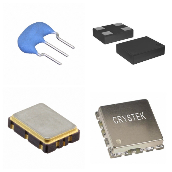
<h1> Crystals, Oscillators, Resonators </h1> <p> Crystals, oscillators and resonators each have their own characteristics and different application scenarios. In actual design, frequency stability, power consumption, cost and environmental factors need to be considered comprehensively. </p> <h2> 1. What are Crystals? </h2> <p> <strong>Definition</strong>: Crystals are typical passive devices (Passive Device), the main component of which is quartz (SiO₂), which use the piezoelectric effect to realize the mutual conversion of mechanical vibration and electrical signals. </p> <p> <strong>Working principle</strong>: When an external voltage is applied, the crystal generates a resonant signal of a fixed frequency through mechanical vibration, but it does not have the driving ability itself and needs to rely on external circuits (such as amplifiers and load capacitors) to maintain oscillation. </p> <p> <strong>Application scenario</strong>: Commonly used in clock circuits (such as microcontrollers and communication equipment) to provide reference frequency, and the nominal frequency range covers kHz to MHz (such as 32.768kHz or 24MHz). </p> <h2> 2. What are Oscillators? </h2> <p> <strong>Definition</strong>: Oscillators are active devices (Active Device), which integrate internal amplifier circuits, feedback resistors and voltage stabilization components, and can independently generate stable frequency signals. </p> <p> <strong>Core features</strong>: </p> <p> √Directly output clock signals (such as sine waves or square waves) without external driving circuits. </p> <p> √Pins usually include power supply (VCC), ground (GND), output (OUT), etc., and the operating voltage supports 1.8V to 5V. </p> <p> √High frequency stability, less affected by temperature and voltage fluctuations, suitable for high-precision scenarios (such as communication base stations, satellite navigation). </p> <p> <strong>Classification</strong>: Including quartz crystal oscillators (XO), temperature-compensated oscillators (TCXO), voltage-controlled oscillators (VCXO), etc.. </p> <h2> 3. What are Resonators? </h2> <p> <strong>Definition</strong>: Resonators broadly include crystal resonators (Crystal Resonators) and ceramic resonators (Ceramic Resonators), both of which are passive devices and require external circuit excitation to work. </p> <p> <strong>Difference from crystals</strong>: </p> <p> √Structure: Crystal resonators are composed of a single quartz plate; ceramic resonators use piezoelectric ceramic materials, which are lower in cost but lower in precision. </p> <p> <strong>√Performance</strong>: Crystal resonators have higher frequency stability and lower aging rates; ceramic resonators are suitable for cost-sensitive medium and low-frequency scenarios (such as home appliance control). </p> <h2> 4. Comparison of Crystals, Oscillators and Resonators </h2> <table> <tbody> <tr class="firstRow"> <td width="95" valign="top" style="padding: 0px 7px; border-width: 1px; border-color: windowtext; background: rgb(190, 190, 190);"> <p> Features </p> </td> <td width="146" valign="top" style="padding: 0px 7px; border-width: 1px; border-color: windowtext; background: rgb(190, 190, 190);"> <p> Crystals </p> </td> <td width="176" valign="top" style="padding: 0px 7px; border-width: 1px; border-color: windowtext; background: rgb(190, 190, 190);"> <p> Oscillators </p> </td> <td width="151" valign="top" style="padding: 0px 7px; border-width: 1px; border-color: windowtext; background: rgb(190, 190, 190);"> <p> Resonators </p> </td> </tr> <tr> <td width="95" valign="top" style="padding: 0px 7px; border-left-width: 1px; border-left-color: windowtext; border-right-width: 1px; border-right-color: windowtext; border-top: none; border-bottom-width: 1px; border-bottom-color: windowtext;"> <p> Device Type </p> </td> <td width="146" valign="top" style="padding: 0px 7px; border-left-width: 1px; border-left-color: windowtext; border-right-width: 1px; border-right-color: windowtext; border-top: none; border-bottom-width: 1px; border-bottom-color: windowtext;"> <p> Passive </p> </td> <td width="176" valign="top" style="padding: 0px 7px; border-left-width: 1px; border-left-color: windowtext; border-right-width: 1px; border-right-color: windowtext; border-top: none; border-bottom-width: 1px; border-bottom-color: windowtext;"> <p> Active </p> </td> <td width="151" valign="top" style="padding: 0px 7px; border-left-width: 1px; border-left-color: windowtext; border-right-width: 1px; border-right-color: windowtext; border-top: none; border-bottom-width: 1px; border-bottom-color: windowtext;"> <p> Passive </p> </td> </tr> <tr> <td width="95" valign="top" style="padding: 0px 7px; border-left-width: 1px; border-left-color: windowtext; border-right-width: 1px; border-right-color: windowtext; border-top: none; border-bottom-width: 1px; border-bottom-color: windowtext;"> <p> Drive Requirements </p> </td> <td width="146" valign="top" style="padding: 0px 7px; border-left-width: 1px; border-left-color: windowtext; border-right-width: 1px; border-right-color: windowtext; border-top: none; border-bottom-width: 1px; border-bottom-color: windowtext;"> <p> External Circuit Required </p> </td> <td width="176" valign="top" style="padding: 0px 7px; border-left-width: 1px; border-left-color: windowtext; border-right-width: 1px; border-right-color: windowtext; border-top: none; border-bottom-width: 1px; border-bottom-color: windowtext;"> <p> No External Circuit Required </p> </td> <td width="151" valign="top" style="padding: 0px 7px; border-left-width: 1px; border-left-color: windowtext; border-right-width: 1px; border-right-color: windowtext; border-top: none; border-bottom-width: 1px; border-bottom-color: windowtext;"> <p> External Circuit Required </p> </td> </tr> <tr> <td width="95" valign="top" style="padding: 0px 7px; border-left-width: 1px; border-left-color: windowtext; border-right-width: 1px; border-right-color: windowtext; border-top: none; border-bottom-width: 1px; border-bottom-color: windowtext;"> <p> Output Signal </p> </td> <td width="146" valign="top" style="padding: 0px 7px; border-left-width: 1px; border-left-color: windowtext; border-right-width: 1px; border-right-color: windowtext; border-top: none; border-bottom-width: 1px; border-bottom-color: windowtext;"> <p> Resonant Signal (Amplification Required) </p> </td> <td width="176" valign="top" style="padding: 0px 7px; border-left-width: 1px; border-left-color: windowtext; border-right-width: 1px; border-right-color: windowtext; border-top: none; border-bottom-width: 1px; border-bottom-color: windowtext;"> <p> Direct Output of Stable Clock Signal </p> </td> <td width="151" valign="top" style="padding: 0px 7px; border-left-width: 1px; border-left-color: windowtext; border-right-width: 1px; border-right-color: windowtext; border-top: none; border-bottom-width: 1px; border-bottom-color: windowtext;"> <p> Resonant Signal (Amplification Required) </p> </td> </tr> <tr> <td width="95" valign="top" style="padding: 0px 7px; border-left-width: 1px; border-left-color: windowtext; border-right-width: 1px; border-right-color: windowtext; border-top: none; border-bottom-width: 1px; border-bottom-color: windowtext;"> <p> Typical Applications </p> </td> <td width="146" valign="top" style="padding: 0px 7px; border-left-width: 1px; border-left-color: windowtext; border-right-width: 1px; border-right-color: windowtext; border-top: none; border-bottom-width: 1px; border-bottom-color: windowtext;"> <p> High-precision clock reference </p> </td> <td width="176" valign="top" style="padding: 0px 7px; border-left-width: 1px; border-left-color: windowtext; border-right-width: 1px; border-right-color: windowtext; border-top: none; border-bottom-width: 1px; border-bottom-color: windowtext;"> <p> Clock source for complex systems </p> </td> <td width="151" valign="top" style="padding: 0px 7px; border-left-width: 1px; border-left-color: windowtext; border-right-width: 1px; border-right-color: windowtext; border-top: none; border-bottom-width: 1px; border-bottom-color: windowtext;"> <p> Low-cost, medium and low-frequency circuits </p> </td> </tr> <tr> <td width="95" valign="top" style="padding: 0px 7px; border-left-width: 1px; border-left-color: windowtext; border-right-width: 1px; border-right-color: windowtext; border-top: none; border-bottom-width: 1px; border-bottom-color: windowtext;"> <p> Cost </p> </td> <td width="146" valign="top" style="padding: 0px 7px; border-left-width: 1px; border-left-color: windowtext; border-right-width: 1px; border-right-color: windowtext; border-top: none; border-bottom-width: 1px; border-bottom-color: windowtext;"> <p> Medium </p> </td> <td width="176" valign="top" style="padding: 0px 7px; border-left-width: 1px; border-left-color: windowtext; border-right-width: 1px; border-right-color: windowtext; border-top: none; border-bottom-width: 1px; border-bottom-color: windowtext;"> <p> High </p> </td> <td width="151" valign="top" style="padding: 0px 7px; border-left-width: 1px; border-left-color: windowtext; border-right-width: 1px; border-right-color: windowtext; border-top: none; border-bottom-width: 1px; border-bottom-color: windowtext;"> <p> Low </p> </td> </tr> </tbody> </table> <h2> 5. How to Choose Crystals, Oscillators and Resonators? </h2> <p> <strong>Accuracy First</strong>: Select a crystal or oscillator (such as TCXO) and optimize the circuit with load capacitance. </p> <p> <strong>Cost Sensitive</strong>: Ceramic resonators can replace low-frequency crystals, but pay attention to the problem of temperature frequency deviation. </p> <p> <strong>Power Consumption Limit</strong>: Silicon oscillators (such as MAX7375) are better than traditional discrete solutions in low-power scenarios. </p>
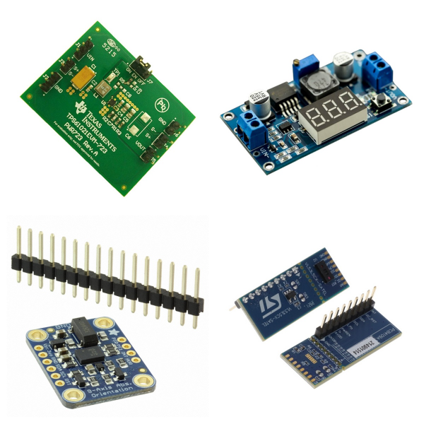
<h1> Development Boards, Kits, Programmers </h1> <h2> 1 What are Development Boards, Kits and Programmers? </h2> <p> Development boards and kits usually include microcontrollers, peripheral interfaces, and debugging modules, providing engineers with a platform to quickly verify designs, test algorithms or learn chip functions. </p> <p> Programmers are used to burn code to the target chip and support firmware updates and debugging. </p> <h2> 2 What are the Main Product Types of Development Boards and Kits? </h2> <p> <strong>Educational Kits</strong>: Such as the educational kits of the Arm University Program, which are designed for teaching scenarios to help students learn the Cortex-M series architecture and embedded development technology. </p> <p> <strong>Cloud Platform Integration Kits</strong>: For example, solutions provided by Enmo Technologies support uploading sensor data from STMicro SensorTile or TI SimpleLink™ SensorTag directly to the cloud. </p> <p> <strong>Wireless Communication Kits</strong>: Such as Nordic Semiconductor's nRF9160 system-in-package (SiP) kit, which integrates cellular IoT and low-power Bluetooth functions. </p> <p> <strong>Display Evaluation Kit</strong>: Such as the E-ink screen development kit of Pervasive Displays, which is used for prototyping of e-paper display modules. </p> <h2> 3 Where are Development Boards and Kits Used for? </h2> <p> <strong>Education and Training</strong>: The learning threshold is lowered through standardized hardware and supporting teaching materials, which is suitable for university laboratories and internal training of enterprises. </p> <p> <strong>Industrial Internet of Things (IIoT)</strong>: Supports sensor data acquisition, edge computing and remote monitoring functions, and is often used for rapid prototyping of smart devices. </p> <p> <strong>Embedded System Development</strong>: Provides debugging interfaces compatible with different chip architectures (such as ARM Cortex-M) to shorten product development cycles. </p> <h2> 4 Typical Manufacturers for Development Boards and Kits </h2> <p> <strong>ARM</strong>: Provides the Versatile Express series development board based on Cortex-M, which supports a variety of peripheral expansions. </p> <p> <strong>Renesas</strong>: The DK-S124 development board is designed for low-power embedded systems and is suitable for sensor networks and wearable devices. </p> <p> <strong>Nordic Semiconductor</strong>: With wireless communication as the core, it launches an integrated development kit that integrates radio frequency (RF) and microcontrollers. </p>

<h1> Discrete Semiconductor Products </h1> <p> Discrete semiconductor devices refer to a collection of semiconductor components with independent packages and single functions, which complement integrated circuits (ICs). </p> <h2> 1. What are the Core Features of Discrete Semiconductor Products? </h2> <p> <strong>Independent packaging</strong>: Each device is packaged separately and can be directly soldered on a circuit board. </p> <p> <strong>Single function</strong>: Focus on achieving specific functions (such as switching, amplification, rectification, etc.). </p> <p> <strong>High flexibility</strong>: Supports building customized circuits by combining discrete devices to adapt to designs with special needs. </p> <h2> 2. What are the Common Types of Discrete Semiconductor Products? </h2> <p> <strong>Diodes</strong>: Used for rectification, voltage regulation (such as Zener diodes), light emission (LED), etc. </p> <p> <strong>Transistors</strong>: </p> <p> <strong>√ Bipolar transistors (BJT)</strong>: Current amplification and switch control. </p> <p> <strong>√ Field effect transistors (MOSFET/IGBT)</strong>: High-frequency switching and power control (such as power supplies, motor drives). </p> <p> <strong>Thyristors</strong>: Used for high-power switches (such as dimmers and motor speed control). </p> <p> <strong>Power devices</strong>: such as power MOSFET, IGBT, etc., support high power density and efficient energy conversion. </p> <h2> 3. Where are Discrete Semiconductor Products Used for? </h2> <p> <strong>Automotive electronics</strong>: such as high-precision LDO series directly connected to the car battery, integrated output protection function. </p> <p> <strong>Power management</strong>: Extend battery life through boost regulators and energy-saving functions (such as nPM2100 PMIC). </p> <p> <strong>Industrial control</strong>: Including motor drive, power conversion, high current switching, and other fields. </p> <p> <strong>RF and signal processing</strong>: such as variable capacitance diodes (Varactor) for RF tuning circuits. </p> <h2> 4. What are the Advantages of Discrete Semiconductor Products? </h2> <p> <strong>High power density</strong>: Provide higher power output in a miniaturized size that is suitable for compact devices. </p> <p> <strong>Low loss and high efficiency</strong>: Reduce energy waste and improve energy utilization efficiency (such as boost regulator applications). </p> <p> <strong>Fast response</strong>: Achieve precise control to meet immediate needs (such as switch control in power conversion). </p> <p> <strong>Temperature Management</strong>: Optimize heat dissipation performance and improve system stability and reliability. </p> <h2> 5. What are Some Examples of Discrete Devices? </h2> <p> MOSFET </p> <p> Bipolar Transistor </p> <p> Transistor Array </p> <p> Transistor with Internal Resistor </p> <p> NSAD Series </p> <p> NNCD Series </p> <p> RD Series </p> <p> SCR </p> <p> TRIAC </p> <p> Trigger Device </p> <h2> 6. Discrete Semiconductor Products FAQs </h2> <h3> 1) How to suppress power supply noise in discrete devices? </h3> <p> In high-speed circuit design, the power supply end of discrete devices needs to adopt a parallel capacitor solution (such as a combination of 0.01μF and a smaller capacitor) to cover the high-frequency band noise suppression requirements; it is also recommended to add a large-capacity capacitor (such as 10μF) at the power supply entrance to improve the overall decoupling effect. </p> <h3> 2) What is the output protection mechanism of discrete devices? </h3> <p> <strong>Short-circuit protection</strong>: Only LVDS output supports short-circuit protection, and it is necessary to ensure that the short-circuit current does not exceed the data sheet limit; LVPECL and CMOS outputs may cause device damage if they are accidentally grounded. </p> <p> <strong>Level limitation</strong>: CMOS output is usually limited to 3.3V LVCMOS level, and direct connection to a 5V system is prohibited to avoid over-voltage risk. </p> <h3> 3) How can discrete devices be synchronized in a multi-chip system? </h3> <p> Multi-chip synchronization requires strict matching of clock signal paths (such as equal-length wiring) and phase alignment through dedicated synchronization pins. For example, ADI clock chips support multi-device synchronization, but they need to be combined with external VCO/VCXO and loop filters to optimize clock stability. </p> <h3> 4) How can discrete devices be more reliable in high-temperature environments? </h3> <p> <strong>Material selection</strong>: Wide bandgap devices (such as SiC and GaN) can work stably in high-temperature environments above 200℃, which is better than traditional silicon-based devices. </p> <p> <strong>Heat dissipation optimization</strong>: It is necessary to use high thermal conductivity packaging (such as copper substrate) or an additional heat sink to reduce junction temperature to extend device life. </p> <h3> 5) What are the configuration requirements for discrete devices to drive different loads? </h3> <p> <strong>Power supply voltage adaptation</strong>: Some devices (such as AD9516) support separate power supply for LVPECL output, and the power supply voltage range needs to be adjusted according to load requirements. </p> <p> <strong>Drive capability matching</strong>: It is necessary to ensure that the output current is compatible with the load impedance, and the drive capability is enhanced by a buffer if necessary. </p> <h3> 6) How to achieve better interface compatibility between discrete devices and digital systems? </h3> <p> <strong>Level conversion</strong>: If the output level of the discrete device does not match the digital system (such as CMOS 3.3V→5V), a level conversion chip or voltage divider circuit needs to be added. </p> <p> <strong>Signal Isolation</strong>: In noise-sensitive scenarios, it is recommended to use optocouplers or magnetic isolation devices to block ground loop interference. </p>
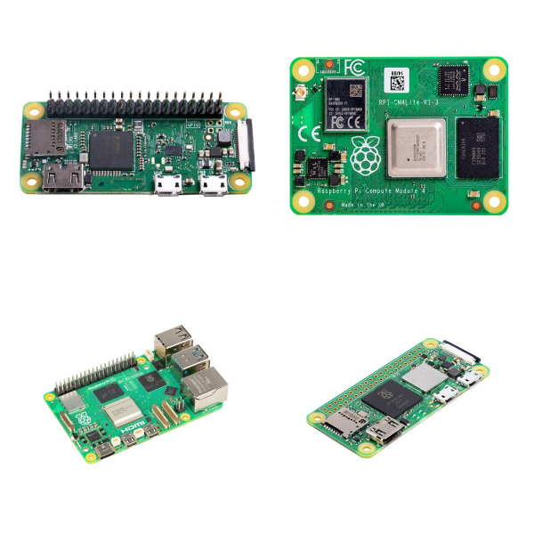
<h1> Embedded Computers </h1> <h2> 1. Embedded Computers Overview </h2> <p> An embedded computer is a special-purpose computer system designed for a specific function. It is usually embedded in mechanical equipment or electrical systems and has the characteristics of real-time computing, high reliability, and low power consumption. Its core features include: </p> <p> Specialization: Optimized design for specific tasks, streamlined and efficient functions. </p> <p> Real-time: Need to respond to events within strict time limits, suitable for scenarios such as industrial control and automotive electronics. </p> <p> Integration: The hardware is highly integrated, usually including modules such as microprocessors, memory, and peripheral interfaces. </p> <h2> 2. What is the Hardware Composition of Embedded Computers? </h2> <p> The hardware architecture of embedded computers mainly includes the following parts: </p> <p> Processor: Adopts microcontroller (MCU) or microprocessor (MPU), such as 8/16/32-bit processor, supports real-time and low power consumption requirements. </p> <p> Memory: Integrated Flash stores program code and RAM is used for runtime data storage. </p> <p> Peripheral interface: Including GPIO, UART, SPI, ADC/DAC, etc., used to connect external devices such as sensors and actuators. </p> <p> Expandability: Some devices support modular expansion (such as CMI technology), which can add communication interfaces or I/O functions. </p> <h2> 3. What is the Software Architecture of Embedded Computers? </h2> <p> Embedded software needs to meet the requirements of solid-state storage, high code quality, and real-time performance. Common architectures include: </p> <p> Real-time operating system (RTOS): manages task scheduling and resource allocation to ensure real-time response. </p> <p> Control loop: Simple systems often use polling mechanisms to handle tasks. </p> <p> Microkernel and exokernel: Suitable for scenarios that require high security and modularity. </p> <h2> 4. Where are Embedded Computers Used for? </h2> <p> Embedded computers are widely used in the following scenarios: </p> <p> Industrial automation: factory controllers, PLC systems, etc. </p> <p> Automotive electronics: engine management, in-car entertainment systems, and autonomous driving modules. </p> <p> Energy Internet of Things: used for smart grids and distributed energy management, supporting real-time data processing and communication. </p> <p> Consumer electronics: home appliance control (such as washing machines, refrigerators), portable devices (smart watches), etc. </p> <h2> 5. Typical Product Examples for Embedded Computers </h2> <p> Advantech embedded single-board computers (SBCs): use compact designs such as Pico-ITX and 3.5 inches, suitable for industrial automation and transportation fields. </p> <p> Cincoze DV-1000 series: support Intel Core processors, have strong and wide temperature characteristics, suitable for energy IoT field terminals. </p> <p> Embedded computers achieve a balance between size, power consumption and performance through the coordinated optimization of software and hardware, becoming the core components of smart devices and IoT systems. </p>
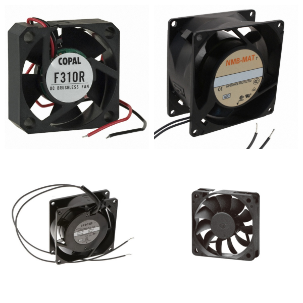
<h1> Fans, Blowers, Thermal Management </h1> <h2> 1.What are Fans, Blowers and Thermal Management? </h2> <p> <strong>Fans and blowers</strong>: They are active heat dissipation devices that remove heat generated by components through forced air flow (thermal convection) to reduce local or system temperature. </p> <p> <strong>Thermal management</strong>: Comprehensive use of heat dissipation design, material selection, and cooling technology to ensure that the temperature of components is within the safe threshold and ensure the stability and life of the equipment. </p> <h2> 2. What is the working principle of Fans, Blowers and Thermal Management? </h2> <p> <strong>Active heat dissipation technology</strong>: </p> <p> <strong>√Fans</strong>: Drive airflow through blade rotation, commonly used in general electronic devices (such as computers and servers). </p> <p> <strong>√Blowers</strong>: Provide higher wind pressure and directional airflow, suitable for scenarios with limited space or centralized heat dissipation (such as avionics packaging). </p> <p> <strong>Heat transfer mechanism</strong>: Heat is dissipated through three paths: thermal conduction (heat sink, thermal pad), thermal convection (forced airflow), and thermal radiation (high emissivity material). </p> <h2> 3. Where are Fans, Blowers and Thermal Management Used for? </h2> <p> <strong>Consumer electronics</strong>: In mobile phones, computers, and other devices, fans are used to dissipate CPU/GPU heat and prevent performance throttling. </p> <p> <strong>High-power devices</strong>: such as high-power chips and LED modules, require blowers or liquid cooling systems to cope with high heat flux density. </p> <p> <strong>Harsh environments</strong>: In scenarios such as avionics, microblowers are preferred due to their low noise and low electromagnetic interference characteristics. </p> <h2> 4. What are the Challenges of Fans, Blowers and Thermal Management? </h2> <p> <strong>Efficiency improvement</strong>: The heat dissipation effect can be enhanced by increasing the heat dissipation area, optimizing the air duct design, or increasing the fan speed, but the noise and energy consumption need to be balanced. </p> <p> <strong>Reliability issues</strong>: Traditional fans may have a shortened life due to mechanical vibration and accumulation of pollutants, and need to be combined with a temperature control system to achieve dynamic adjustment. </p> <h2> 5. What are the Development Trends of Fans, Blowers and Thermal Management? </h2> <p> <strong>Miniaturization and integration</strong>: The combination of micro blowers, heat pipes, and other technologies meets the efficient heat dissipation needs of small devices. </p> <p> <strong>Intelligent temperature control</strong>: Combine temperature sensors with adaptive algorithms to achieve dynamic optimization of heat dissipation strategies. </p>
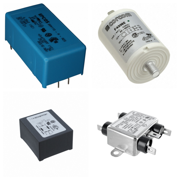
<h1> Filters </h1> <p> Filters can effectively optimize signal integrity and improve the anti-interference ability and performance of electronic systems. </p> <h2> 1. Filters Overview </h2> <p> A filter is an electronic circuit or device used for signal processing. Its core function is to improve signal quality by selectively allowing specific frequency components to pass through while suppressing or attenuating other frequency components. Its application scenarios include communication systems, power management, audio processing, and RF front-end. </p> <h2> 2. What are the Types of Filters? </h2> <h3> 1) Classification by frequency characteristics </h3> <p> Low-pass filter (LPF): allows signals below the cutoff frequency to pass through, suppresses high-frequency noise, and is often used for power supply ripple smoothing. </p> <p> High-pass filter (HPF): allows signals above the cutoff frequency to pass through, and removes low-frequency interference (such as DC offset). </p> <p> Band-pass filter (BPF): only allows signals in a specific frequency band to pass through, and is used for signal frequency division in communication systems. </p> <p> Band-stop filter (BSF): suppresses signals in a specific frequency band (such as ground reflection interference in radar systems). </p> <h3> 2) Classification by implementation method </h3> <p> Passive filter: composed of passive components such as resistors, capacitors, and inductors, with low cost, but performance limited by component parameters. </p> <p> Active filter: combined with active components such as operational amplifiers, with high gain and strong stability. </p> <p> Digital filter: processes discrete signals through algorithms (such as FIR and IIR filters) with high flexibility. </p> <h3> 3) Special Types </h3> <p> RF filter: used in wireless communication equipment (such as mobile phones and base stations) to solve the problem of interference between frequency bands. Typical types include surface acoustic wave filters (SAW) and bulk acoustic wave filters (BAW). </p> <h2> 4. What are the Key Performance Parameters of Filters? </h2> <p> Center frequency: the reference frequency of the filter passband (such as the midpoint frequency of the bandpass filter). </p> <p> Bandwidth: the frequency range allowed to pass. </p> <p> Q value (quality factor): the core indicator for measuring frequency selectivity. The higher the Q value, the stronger the frequency selectivity of the filter. </p> <p> Insertion loss: the power loss when the signal passes through the filter, which needs to be reduced as much as possible. </p> <h2> 5. Where are Filters Used for? </h2> <h3> 1) Communication system </h3> <p> Transmitter: located behind the power amplifier (PA) to filter out harmonic interference. </p> <p> Receiver: located in front of the low noise amplifier (LNA) to suppress out-of-band noise. </p> <h3> 2) Power management </h3> <p> Filter out ripple and noise in the power supply voltage and provide stable DC output. </p> <h3> 3) Biomedicine and image processing </h3> <p> A high-pass filter enhances image edge details, and a band-stop filter removes interference in specific frequency bands. </p> <h2> 6. How to Choose Filters? </h2> <p> Application scenario requirements: Base station filters require high power capacity and stability, and mobile phone filters require miniaturization and low cost. </p> <p> Environmental interference type: Select low-pass, high-pass, or band-stop type according to the noise frequency band. </p> <p> Integration process: SMT (surface mount technology) is suitable for miniaturized RF filter design. </p> <h2> 7. Typical Brands for Filters </h2> <p> SCHURTER </p> <p> MOLEX </p> <p> TDK </p> <p> Murata </p> <p> Xilinx </p> <p> TI </p> <h2> 8. Filters FAQs </h2> <h3> 1) How do filters work? </h3> <p> Filters achieve their functions through a frequency selection mechanism: they allow signals to pass with minimal attenuation in the passband, while greatly attenuating interference signals in the stopband. For example, a low-pass filter allows low-frequency signals to pass while suppressing high-frequency noise. </p> <h3> 2) What is the core difference between digital filters and analog filters? </h3> <p> Analog filters: They are composed of passive components such as resistors, capacitors, and inductors, and process continuous-time signals. They have a simple structure but low adjustment flexibility. </p> <p> Digital filters: They process discrete signals based on algorithms, have strong programmability, and are suitable for high-precision scenarios (such as IIR/FIR filters in communication systems). </p> <h3> 3) What should be noted when installing filters? </h3> <p> Wiring requirements: Reserve a "clean ground" at the cable port to avoid direct coupling between the signal ground and the filter ground. </p> <p> Electromagnetic shielding: The filter and the chassis must be reliably overlapped, and metal plates or sealing gaskets must be used to reduce RF impedance when necessary. </p> <p> Installation location: Keep as close to the interference source or sensitive equipment as possible to shorten the length of the wire after filtering. </p> <h3> 4) What are the special requirements for RF filters? </h3> <p> High-frequency performance: Need to support GHz frequency bands, such as SAW/BAW filters commonly used in 5G communications. </p> <p> Manufacturing process: Use surface acoustic wave (SAW) or bulk acoustic wave (BAW) technology to improve quality factor and temperature stability. </p> <h3> 5) What are the common causes of filter failure? </h3> <p> Environmental factors: High temperature causes capacitor capacitance drift, and high humidity causes leakage current or component corrosion. </p> <p> Overload damage: Exceeding the rated voltage/current causes inductor saturation or capacitor breakdown. </p> <p> Design defects: Failure to match system impedance causes signal reflection or abnormal insertion loss. </p>
<h1> Hardware, Fasteners, Accessories </h1> <h2> 1. Hardware Overview </h2> <p> Structural parts and support parts </p> <p> Includes basic physical structural parts such as equipment housing, brackets, and guide rails, which are used to protect internal circuits or provide installation frames. For example, metal/plastic housings can shield electromagnetic interference, and PCB board support frames are used to fix the position of circuit boards. </p> <p> Installation tools and auxiliary equipment </p> <p> Involves welding tools (such as soldering irons), PCB punching equipment, etc., which are used for physical assembly and debugging of components. For example, soldering irons are used to solder discrete components or connect wires. </p> <h2> 2. Fasteners Overview </h2> <p> Mechanical connection elements </p> <p> Includes standard parts such as screws, nuts, and washers, which are used to fix components in electronic devices. For example, screws are used to fix heat sinks and chips, and spring washers can prevent loosening caused by vibration. </p> <p> Special fixing devices </p> <p> Such as non-threaded fixing solutions such as buckles, cable ties, and adhesives. For example, nylon cable ties are used for cable management, and thermal conductive adhesives are used to bond heat sinks and power devices. </p> <h2> 3. Accessories Overview </h2> <p> Connection accessories </p> <p> Includes interface components such as plugs, sockets, and pin headers, which are used for detachable connections between circuits. For example, USB interface modules are standardized connection accessories, and female headers are used to connect expansion boards to motherboards. </p> <p> Functional expansion accessories </p> <p> Such as auxiliary modules that enhance device functions, such as cooling fans, LED indicators, and buzzers. For example, cooling fans reduce the temperature of high-power components through active heat dissipation, and LED lights are used for status indication. </p> <p> Protection and maintenance accessories </p> <p> Includes dust screens, anti-static wrist straps, fuses, etc. For example, fuses are used for overcurrent protection, and anti-static accessories can prevent components from being damaged by static electricity breakdown. </p> <h2> 4. Where are Hardware, Fasteners and Accessories Used for? </h2> <p> Consumer electronics: mobile phone housing (hardware) + internal screws (fasteners) + Type-C interface (accessories) </p> <p> Industrial equipment: cabinet rails (hardware) + cooling fans (accessories) + grounding bolts (fasteners) </p>
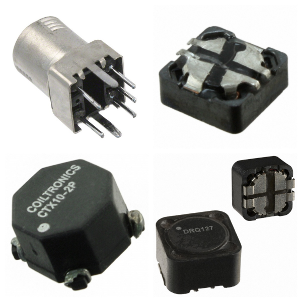
<h1> Inductors, Coils, Chokes </h1> <p> All three are essentially inductors, and the differences in their names stem from the different emphasis on design goals, structural features, and application scenarios. </p> <h2> 1. What are Inductors, Coils and Chokes? </h2> <p> Inductor: A passive component that uses the self-inductance effect as its core principle to store magnetic energy and resist current changes through the principle of electromagnetic induction. Its basic functions include filtering, oscillation, waveform transformation, and cooperating with capacitors to achieve resonant circuits. </p> <p> Coil: A multi-turn wire structure wound by enameled wire, usually as a physical implementation form of an inductor, widely used in electromagnets, transformers, radio transmitters, and other scenarios. </p> <p> Choke: A specially designed inductor that is used to suppress high-frequency AC signals (such as radio frequency interference) while allowing DC or low-frequency current to pass. Its core function is to block unnecessary AC components through high reactance. </p> <h2> 2. What are the Structural Differences between Coils and Chokes? </h2> <p> Coil: Usually a hollow or cored winding structure, the core material (such as ferrite, alloy powder core) can significantly increase the inductance value. For example, the "tank circuit" in the radio transmitter often uses a high-Q hollow coil. </p> <p> Choke: The design emphasizes high-frequency impedance characteristics, often using core materials and optimizing the winding method to reduce distributed capacitance. For example, the high-frequency noise of the switching power supply is suppressed by the choke in the power supply filter circuit. </p> <h2> 3. What are Inductors, Coils and Chokes Used for? </h2> <h3> 1)Coil: </h3> <p> Electromagnetic equipment: such as transformer windings, and relay coils. </p> <p> High-frequency circuits: such as RF matching networks, and antenna tuning. </p> <h3> 2)Choke: </h3> <p> Power supply circuit: suppress AC ripple in DC power supply. </p> <p> Signal processing: block radio frequency interference (RFI) from entering sensitive circuits. </p> <h3> 3)Inductor (general purpose): </h3> <p> Energy storage and filtering: such as energy storage elements in LC filter circuits. </p> <p> Energy conversion: such as step-up/step-down inductors in switching power supplies. </p> <h2> 4. Reasons for Naming Differences </h2> <p> Function-oriented naming: For example, "choke" emphasizes its function of suppressing AC ("Choke" means "choke"), while "coil" focuses on the physical structure description. </p> <p> Application scenario distinction: For example, "winding" is used to describe the coil in a motor or transformer, emphasizing its role in energy transmission; "bead" specifically refers to a small inductor used for high-frequency filtering. </p> <h2> 5. Typical Brands for Inductors, Coils and Chokes </h2> <p> BOURNS </p> <p> TDK </p> <p> VISHAY </p> <p> ABRACON </p> <p> Murata </p> <p> TOKO </p> <h2> 6. Inductors, Coils and Chokes FAQs </h2> <h3> 1) What are the differences between inductors, coils, and chokes? </h3> <p> Inductors are mainly used for energy storage and filtering; </p> <p> Coils refer to general components with winding structures; </p> <p> Chokes are inductors specifically used to suppress high-frequency noise, commonly found in power supplies and RF circuits. </p> <h3> 2) How do chokes achieve high-frequency signal isolation? </h3> <p> Chokes use the high-frequency impedance characteristics of inductors (XL=ωL) to allow DC and low-frequency signals to pass while blocking high-frequency interference. For example, RF chokes can limit high-frequency noise to local circuits. </p> <h3> 3) What parameters should be considered when selecting chokes? </h3> <p> Key parameters include inductance value, tolerance (such as ±20%), saturation current (such as 3.75A), DC resistance (such as 37mΩ), and self-resonant frequency (such as 65MHz). Common-mode chokes also need to consider common-mode impedance (such as 300Ω). </p> <h3> 4) How should inductors be selected in high-frequency circuit design? </h3> <p> Shielded inductors (such as Power Shielded Inductors) should be preferred to reduce electromagnetic interference; high-frequency transformers should adopt planar or ferrite core designs to optimize performance. </p> <h3> 5) In what scenarios do common-mode chokes need to be used? </h3> <p> Common-mode chokes (such as 744212510 models) are often used to suppress common-mode noise in power lines or communication lines and are suitable for EMI filtering and high-speed data transmission systems. </p> <h3> 6) What is the role of chokes in radio frequency (RF) circuits? </h3> <p> In broadband communications (such as fiber optic networks), RF chokes can isolate high-frequency interference in signal paths to ensure signal integrity. </p> <h3> 7) What are the design points of high-frequency transformers? </h3> <p> The core material (such as ferrite), winding structure, and shielding process need to be optimized to meet high-frequency efficiency and low-loss requirements. Planar transformers are widely used due to their small size and good heat dissipation. </p> <h3> 8) How does the packaging form of high-power inductors affect performance? </h3> <p> For example, SMD packaged inductors such as the IHLP1616BZET1R0M01 use molded composite cores and combine high current carrying capacity (such as 10.5A saturation current) with compact size (4.06×4.06×1.8mm). </p>
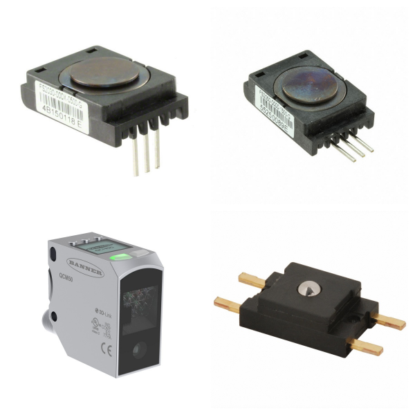
<h1> Industrial Automation and Controls </h1> <h2> 1. What are the Core Components of Industrial Automation Products? </h2> <h3> 1)Controller </h3> <p> <strong>PLC (Programmable Logic Controller)</strong>: As the "brain" of the industrial automation system, PLC implements logical operations, data processing and equipment communication through programming, replacing the traditional relay system, and has high reliability, flexibility and scalability. </p> <p> <strong>Intelligent controller</strong>: Supports complex algorithms and multi-device collaborative control, and is widely used in production lines, energy management and other scenarios. </p> <h3> 2)Sensors and actuators </h3> <p> <strong>Sensors</strong>: Including temperature, pressure, photoelectric and other types, used to monitor physical quantities in real time and convert them into electrical signals to provide data input for the system. </p> <p> <strong>Electric actuator</strong>: Drive mechanical movement through electric motors to achieve precise control of equipment such as valves and conveyor belts, support remote operation, and automated processes. </p> <h3> 3)Auxiliary components </h3> <p> <strong>Circuit breakers and relays</strong>: Ensure circuit safety, and achieve signal isolation and load control. </p> <p> <strong>Inverter and servo system</strong>: Used for motor speed regulation and precision motion control to improve production efficiency and energy consumption management. </p> <h2> 2. Where are Industrial Automation Products Used for? </h2> <p> <strong>Production line automation</strong>: Monitor parameters through sensors and adjust equipment status through PLC to ensure product quality and production efficiency. </p> <p> <strong>Energy and environmental management</strong>: Applied to pumping stations, sewage treatment, exhaust gas monitoring, and other systems to achieve remote control and energy-saving optimization. </p> <p> <strong>Intelligent manufacturing</strong>: Combined with machine vision (industrial cameras), 3D modeling, and other technologies, promote flexible manufacturing and smart factory construction. </p> <h2> 3. What are the Technical Features of Industrial Automation Products? </h2> <p> <strong>Programmability</strong>: Support flexible configuration of control logic to adapt to diverse industrial scenarios. </p> <p> <strong>High precision and reliability</strong>: Millimeter-level control is achieved through components such as encoders and gratings to ensure long-term stable operation of the system. </p> <p> <strong>System integration</strong>: Supports interconnection with MES, SCADA, and other systems to build a data-driven remote monitoring and management platform. </p> <h2> 4. What are the Frontier Trends of Industrial Automation Products? </h2> <p> <strong>Intelligent sensors</strong>: Integrate edge computing capabilities to achieve real-time data analysis and local decision-making. </p> <p> <strong>Modular design</strong>: Simplify equipment deployment and maintenance through standardized interfaces (such as communication modules). </p> <p> <strong>Green Automation</strong>: Optimize energy consumption algorithms and integrate renewable energy to promote sustainable development. </p>
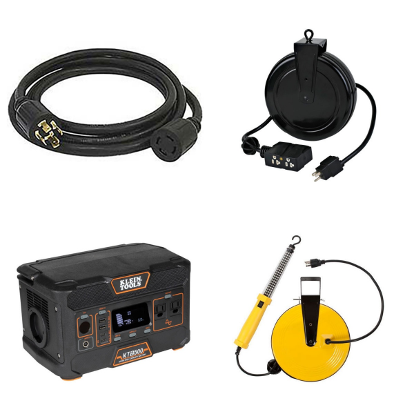
<h1> Industrial Supplies </h1> <p> Industrial supplies encompass a wide range of products used by a variety of industries to support operations, maintenance, and manufacturing processes. These supplies include tools, equipment, and consumables necessary for daily activities in industrial settings. It includes categories such as appliances, fans, HVAC, office equipment, and furniture, as well as a range of protective equipment including gloves and safety gear, and maintenance and cleaning supplies. These items are essential to ensuring safety, efficiency, and productivity in workplaces such as factories, construction sites, warehouses, and other industrial settings. </p>
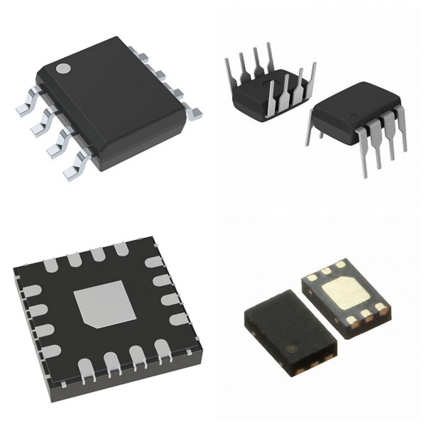
<h1> Integrated Circuits (ICs) </h1> <h2> 1. Integrated Circuits (ICs) Overview </h2> <p> Integrated Circuits is a microelectronic device that integrates electronic components such as transistors, resistors, capacitors, inductors, etc. on semiconductor chips (such as silicon or gallium arsenide) or dielectric substrates through specific processes. All components form a whole structure, with the characteristics of miniaturization, low power consumption, high reliability, etc., and are represented by "IC" in the circuit. </p> <h2> 2. What are the Types of Integrated Circuits (ICs)? </h2> <p> According to functions and application scenarios, ICs are mainly divided into the following categories: </p> <p> <strong>Analog integrated circuits</strong>: Processing continuous signals, such as operational amplifiers and sensor signal conditioning chips. </p> <p> <strong>Digital integrated circuits</strong>: Processing discrete digital signals, including logic gates, microprocessors, memories, etc. </p> <p> <strong>Mixed-signal integrated circuits</strong>: Combining analog and digital functions, such as analog-to-digital converters (ADCs) and digital-to-analog converters (DACs). </p> <p> <strong>Power ICs</strong>: Focusing on power management and driving, such as power management chips (PMICs) and driver chips (Driver ICs), are widely used in smartphones, automobiles, and industrial equipment. </p> <p> <strong>RF/Microwave ICs</strong>: used in high-frequency communication systems, such as 5G RF chips and microwave filters. </p> <h2> 3. What are Integrated Circuits (ICs) Used for? </h2> <p> <strong>Communication Technology</strong>: Processors and RF chips in smartphones, and high-speed data transmission modules for 5G base stations. </p> <p> <strong>Medical Equipment</strong>: Low-power control chips for wearable health monitoring devices (such as smartwatches) and implantable devices (such as pacemakers). </p> <p> <strong>Automotive Electronics</strong>: Sensor processing chips for autonomous driving systems, vehicle-to-everything (V2X) communication modules, and battery management systems (BMS) for electric vehicles. </p> <p> <strong>Computers and Consumer Electronics</strong>: High-performance computing chips such as CPUs and GPUs, as well as control units in home appliances. </p> <p> <strong>Industry and Internet of Things</strong>: Low-power chips for industrial automation controllers and Internet of Things nodes. </p> <h2> 4. What are the Main Features of Integrated Circuits (ICs)? </h2> <p> <strong>High Integration</strong>: Nanoscale component density is achieved through processes such as photolithography, and performance is continuously improved in accordance with Moore's Law. </p> <p> <strong>Low-power Design</strong>: CMOS technology is used to reduce energy consumption, suitable for mobile devices and wearable technology. </p> <p> <strong>Reliability</strong>: Packaging technology (such as QFN, and BGA) improves anti-interference ability and environmental adaptability. </p> <h2> 5. What are the Manufacturing Process of Integrated Circuits (ICs)? </h2> <p> <strong>Design and verification</strong>: Circuit design and simulation are completed through EDA tools. </p> <p> <strong>Wafer processing</strong>: Circuit structure is formed on silicon wafers through deposition, lithography, etching, and other processes. </p> <p> <strong>Packaging test</strong>: After cutting the wafer, it is packaged into independent chips, and functional and reliability tests are performed. </p> <h2> 6. What are the Industry Trends of Integrated Circuits (ICs)? </h2> <p> With the popularization of 5G, artificial intelligence and electric vehicles, the demand for high-performance, low-power ICs continues to grow. In 2024, the global power ICs market size has exceeded US$21.5 billion, and it is expected to expand further in the fields of smart driving and green energy in the future. </p> <h2> 7. Typical Brands for Integrated Circuits (ICs) </h2> <p> NXP </p> <p> DIODES </p> <p> ST </p> <p> ON </p> <p> TI </p> <h2> 8. Integrated Circuits (ICs) FAQs </h2> <h3> 1) What are the core components and materials of ICs? </h3> <p> <strong>Material</strong>: Semiconductor wafers are mainly based on silicon (Si) or germanium (Ge), with silicon being the mainstream in modern times. </p> <p> <strong>Composition</strong>: Transistors, resistors, capacitors, and interconnect wiring are integrated into semiconductor substrates through processes such as lithography, diffusion, and oxidation. </p> <h3> 2) What key technologies are involved in the manufacturing of ICs? </h3> <p> <strong>Core Processes</strong>: Oxidation, lithography, diffusion, epitaxial growth, metal evaporation, etc. </p> <p> <strong>Design Technology</strong>: Including circuit design, layout and packaging testing, etc. </p> <h3> 3) What are the Advantages of ICs over discrete component circuits? </h3> <p> <strong>Volume and Weight</strong>: Highly integrated, greatly reducing circuit size. </p> <p> <strong>Performance</strong>: Low power consumption, high reliability, and suitable for mass production. </p> <p> <strong>Cost</strong>: The cost of mass production is lower than that of discrete component combinations. </p> <h3> 4) What are the common methods for IC failure analysis? </h3> <p> <strong>Electrical Analysis</strong>: Curve tracer (CT) detects short circuits/open circuits, and parameter analyzer evaluates transistor performance. </p> <p> <strong>Optical Inspection</strong>: Infrared microscopy locates internal defects, and thermal emission microscopy (TIVA/OBIRCH) detects leakage current points. </p>
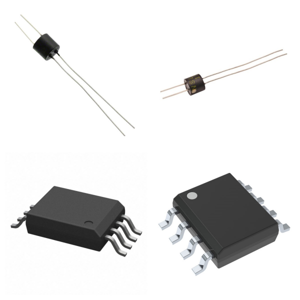
<h1> Isolators </h1> <p> Isolators are key components used to achieve electrical isolation in electronic circuits. Their main function is to block direct electrical connections between different circuits while allowing unidirectional transmission of signals or energy, thereby improving the safety and anti-interference ability of the system. The following is a detailed description of its core features and application scenarios: </p> <h2> 1. Isolators Overview </h2> <h3> 1)Basic composition </h3> <p> Usually composed of optical couplers or transformers, and some high-frequency scenarios use RF-specific structures. </p> <p> There are various packaging forms, such as direct plug-in type, surface mount type (SMD), etc. Some high-end models use hermetic packaging to enhance weather resistance. </p> <h3> 2)Core functions </h3> <p> <strong>Electrical isolation</strong>: Isolate high-voltage and low-voltage circuits to prevent abnormal current flow from causing damage to equipment or personnel. </p> <p> <strong>Signal transmission</strong>: Realize cross-isolation transmission of signals through electromagnetic induction or photoelectric conversion to avoid ground loop interference. </p> <p> <strong>Decoupling and filtering</strong>: Separate DC components and AC noise in the power supply circuit to improve system stability. </p> <h2> 2. What are Isolators Used for? </h2> <p> <strong>Power supply and industrial system</strong> </p> <p> Decoupling circuit for power module to suppress high-frequency noise interference. </p> <p> Isolate control circuits and execution circuits in industrial automation equipment to prevent high-voltage shock from damaging sensitive components. </p> <p> <strong>Communication and RF field</strong> </p> <p> RF isolators (such as MACOM MADL series) are used in high-frequency systems such as wireless communication and radar, supporting 1 GHz to 2 GHz frequency bands, with an impedance of 50Ω to ensure the stability of signal transmission. </p> <p> Protect the front-end circuit of the receiver to avoid equipment damage caused by signal reflection. </p> <p> <strong>Medical and precision equipment</strong> </p> <p> Isolate the patient side from the main control circuit in medical equipment to ensure safety and compliance. </p> <p> Block common-mode interference in precision measuring instruments to improve signal acquisition accuracy. </p> <h2> 3. How to Choose Isolators? </h2> <h3> 1)Key parameters </h3> <p> <strong>Frequency range</strong>: For example, the RF isolator needs to match the system operating frequency band (such as 1.3 GHz). Insertion loss: Typical value is as low as 0.35 dB, reducing signal attenuation. </p> <p> <strong>Temperature resistance</strong>: The operating temperature range is usually -65°C to 125°C. </p> <h3> 2)Classification and selection recommendations </h3> <p> <strong>Photoelectric coupling type</strong>: Suitable for low-frequency signal isolation, and low cost. </p> <p> <strong>Transformer coupling type</strong>: Supports high frequency and energy transmission, but has a larger volume. </p> <p> <strong>RF dedicated type</strong>: Optimized for high-frequency scenarios, attention should be paid to impedance matching and packaging form. </p> <h2> 4. Typical Brands for Isolators </h2> <p> Infineon </p> <p> TOSHIBA </p> <p> Onsemi </p> <p> TI </p> <p> VISHAY </p> <p> LITEON </p> <h2> 5. Isolators FAQs </h2> <h3> 1) How do Isolators work? </h3> <p> <strong>Photocoupler</strong>: The input LED emits light, and the photosensitive element (such as a phototransistor) receives the light signal and converts it into an electrical signal, realizing no direct electrical connection between the input and the output. </p> <p> <strong>Capacitive Isolator</strong>: Through high-frequency signal modulation, energy or data is transferred using the capacitor medium, blocking DC and low-frequency interference. </p> <p> <strong>Inductive Isolator</strong>: Energy or signal is transferred using magnetic field coupling, isolating the primary and secondary circuits. </p> <h3> 2) What are the common failure mechanisms of Isolators and how to avoid them? </h3> <p> <strong>Optical Attenuation of Optocouplers</strong>: LED aging causes signal transmission failure, so it is necessary to select high-reliability models and avoid long-term overload. </p> <p> <strong>Capacitive Isolation Breakdown</strong>: Overvoltage or dielectric aging causes short circuits, so it is necessary to strictly limit the operating voltage and add protection circuits. </p> <p> <strong>Inductive Isolation Saturation</strong>: The magnetic field is too strong, resulting in a decrease in efficiency, and the core material and drive current need to be optimized. </p> <h3> 3) How to determine whether the isolation level of Isolators meets the requirements? </h3> <p> The isolation level needs to be comprehensively evaluated based on the system's maximum operating voltage, transient overvoltage (such as lightning strikes or switching surges), and safety standards (such as IEC 61010). For example, medical equipment usually requires reinforced isolation (such as 5000Vrms), while industrial control scenarios may only require basic isolation (2500Vrms). </p> <h3> 4) What factors affect the life of isolators? </h3> <p> <strong>Optocoupler</strong>: LED light decay is the main factor. Long-term high temperature or overcurrent will accelerate aging. It is recommended to control the forward current within 60% of the rated value. </p> <p> <strong>Capacitive Isolator</strong>: The aging of the dielectric material or moisture penetration may cause capacitance drift. Moisture-resistant packaging (such as ceramic dielectric) is required. </p> <p> <strong>Solid-State Relay</strong>: The number of switching times and load type (capacitive/inductive) affect the contact life. The life under resistive load can reach more than 10^7 times. </p> <h3> 5) What are the common design issues of isolators in I2C communication? </h3> <p> <strong>Bidirectional Signal Conflict</strong>: Direct use of unidirectional isolators will cause bus latch failure. It is necessary to select a dedicated isolation I2C chip (such as ISO1540) or implement bidirectional isolation through an external logic circuit. </p> <p> <strong>Signal Delay</strong>: The transmission delay of the isolation device must be less than the minimum clock cycle of the I2C bus. For example, a 100kHz bus requires a delay of ≤ 1μs. </p> <p> <strong>Power Consumption Matching</strong>: The pull-up resistor values on both sides of the isolator must match the bus driving capability to avoid abnormal logic levels due to impedance mismatch. </p> <h3> 6) What is the difference between isolators and other protection devices (such as TVS diodes)? </h3> <p> <strong>Functional Difference</strong>: Isolators achieve electrical isolation and block common-mode interference and ground loops; TVS diodes are mainly used to suppress transient overvoltages (such as ESD) and belong to clamping protection. </p> <p> <strong>Application Scenarios</strong>: Isolators are suitable for long-term isolation needs (such as power systems), while TVS diodes are used for short-term pulse protection (such as communication ports). </p> <p> <strong>Cooperative Use</strong>: In a high-voltage environment, isolators and TVS diodes can be connected in series, the former isolating continuous interference, and the latter absorbing transient energy. </p> <h3> 7) How to test the isolation performance of isolators? </h3> <p> <strong>Withstand Voltage Test</strong>: Use a withstand voltage tester to apply isolation voltage (such as 3000Vrms/1 minute) to detect whether the leakage current exceeds the standard (usually ≤ 1mA). </p> <p> <strong>Transmission Characteristics Test</strong>: Input a square wave through a signal generator, and observe the waveform distortion and delay at the output end with an oscilloscope to verify whether the bandwidth meets the standard. </p> <p> <strong>Temperature Rise Test</strong>: Continuously operate at the highest operating temperature to monitor whether the isolation medium has a breakdown or parameter drift. </p> <h2> 6. Summary </h2> <p> Isolators ensure circuit safety and signal integrity through physical isolation and are indispensable components in power supply, communication, industry, and medical fields. When selecting, it is necessary to consider the frequency requirements, isolation strength, and packaging form. </p>
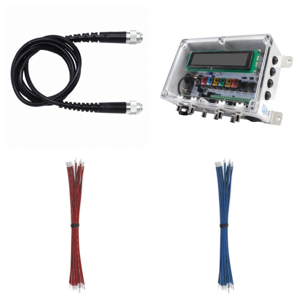
<h1> Kits </h1> <p> A kit product is a collection of similar items that differ in some way and are intended to be convenient for development, repair, or evaluation purposes. For example, common gauge wire of different colors, timing crystals of different frequencies, resistors or inductors of different values, fuses of different sizes and current ratings, heat shrink tubing of different sizes, LEDs of different colors, etc. </p>
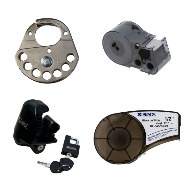
<h1> Labels, Signs, Barriers, Identification </h1> <p> Label, Sign, Barrier and Identification products include printable and preprinted labels for non-wire/cable applications, LOTO (lockout/tagout) supplies, warning and advisory signs, adhesive hazard warning and advisory stickers, floor markings, identification and maintenance labels, and other products designed for general marking, identification, hazard mitigation and similar purposes. </p>
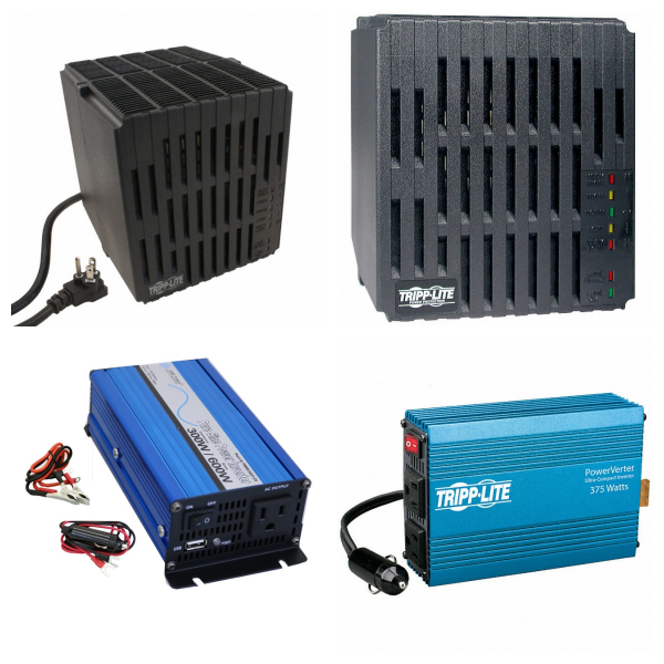
<h1> Line Protection, Distribution, Backups </h1> <p> Products in the Line Protection, Power Distribution, and Backup categories are finished products designed to operate from standard AC mains power or equipment requiring that power, including multi-outlet power strips, battery backup systems, surge protection and noise filtering devices, and DC to AC power conversion. Also included are accessories designed specifically for use with these products, such as replacement battery packs and interface cables. </p>
<h1> Magnetics - Transformer, Inductor Components </h1> <h2> 1. What are the Core Types of Magnetic Components? </h2> <p> Transformer: used for voltage conversion, circuit isolation and energy transfer, its design needs to combine core materials and winding structures to optimize efficiency. </p> <p> Inductor: plays a key role in filtering, energy storage and resonant circuits, and high-frequency applications need to consider core saturation characteristics and loss control. </p> <p> Integrated magnetic components: such as planar magnetic components, coreless PCB transformers, etc., improve power density through miniaturization design, suitable for high-frequency switching power supplies. </p> <h2> 2. What are the Technical Features of Magnetic Components? </h2> <p> High-frequency Performance Optimization: for high-frequency switching converters (such as DC-DC), the core material needs to reduce eddy current losses, and the winding layout needs to reduce parasitic parameters. </p> <p> Core Structure Innovation: including split core design (such as upper and lower core splicing), multi-axis flux path, etc., to improve heat dissipation and prevent magnetic saturation. </p> <p> Temperature and Reliability Management: improve the stability of components in high temperature environments through core material selection (such as ferrite) and packaging process. </p> <h2> 3. What are Magnetic Components Used for? </h2> <p> Power Conversion Systems: Energy storage and transfer in AC-DC rectifiers and DC-DC converters. </p> <p> Signal Isolation and Coupling: Physical isolation between circuits in communication equipment to reduce noise interference. </p> <p> IC Integration: Micro inductors or transformers can be directly embedded in chips for use in RF circuits or power management modules. </p> <h2> 4. What is the Core Difference between Transformers and Inductors? </h2> <p> Functional Differences: </p> <p> Inductors mainly convert electrical energy into magnetic energy storage and hinder instantaneous changes in current. </p> <p> Transformers are used to achieve voltage conversion, energy transfer, and circuit isolation through electromagnetic induction. </p> <p> Structural Features: </p> <p> Inductors are usually single-winding structures, while transformers contain at least two sets of mutually insulated windings. </p> <p> Transformers need to achieve energy transfer through magnetic core coupling, and the inductor core may be hollow or magnetic material. </p> <h2> 5. Product Examples of Inductor Components </h2> <p> Ferroxcube CP-P14/8-2S: A typical ferrite core inductor suitable for high-frequency power filtering with low loss and high temperature stability. </p> <h2> 6. Magnetic Components FAQs </h2> <h3> 1) What are the main application scenarios of magnetic components? </h3> <p> Inductors: </p> <p> Power filtering (such as suppressing high-frequency noise); </p> <p> Resonant circuits (such as wireless charging and RF modules); </p> <p> Dynamic current control (such as energy storage elements in switching power supplies). </p> <p> Transformer: </p> <p> Voltage conversion (such as AC/DC adapter, power transmission); </p> <p> Signal isolation (such as communication interface, medical equipment); </p> <p> Power converter (such as energy coupling in LLC resonant topology). </p> <h3> 2) How do the distributed parameters of magnetic components affect circuit performance? </h3> <p> Eddy current loss: Eddy currents generated by core materials at high frequencies cause heating, and the core lamination or powder pressing process needs to be optimized; </p> <p> Parasitic capacitance: The capacitance between winding layers may cause resonance peaks, which need to be suppressed by staggered winding or shielding layer design; </p> <p> Leakage inductance effect: The magnetic field that is not fully coupled by the transformer will form leakage inductance, and a buffer circuit needs to be reserved in the topology design. </p> <h3> 3) How to test the key parameters of magnetic components? </h3> <p> Inductance measurement: Use an LCR meter to test at a specified frequency (such as 1kHz-1MHz); </p> <p> Saturation current test: Gradually increase the DC bias current and observe the critical point where the inductance drops to the nominal value; </p> <p> Temperature rise experiment: Monitor the core and winding temperature during full load operation and evaluate the heat dissipation design. </p> <h3> 4) What is the future development trend of magnetic components? </h3> <p> High frequency: Adapt to the high-frequency switching requirements of GaN/SiC devices and develop low-loss core materials; </p> <p> Integration: Integrate magnetic components with PCB (such as planar transformers) to improve power density; </p> <p> Intelligence: Embed sensors to monitor temperature and current status in real time and realize fault warnings. </p> <h3> 5) How will the performance of magnetic components change in high-temperature environments? </h3> <p> Attenuation of magnetic core characteristics: </p> <p> The magnetic permeability of ferrite decreases with increasing temperature (failure after exceeding the Curie temperature), so it is necessary to select high Curie point materials (such as manganese-zinc ferrite); </p> <p> The eddy current loss of silicon steel sheets increases at high temperatures, so the operating temperature range needs to be limited. </p> <p> Reduced winding reliability: </p> <p> The insulation layer of enameled wire is prone to aging at high temperatures, and polyimide or Teflon coated wire is recommended. </p> <h3> 6) How to suppress electromagnetic interference (EMI) of magnetic components in high-frequency circuits? </h3> <p> Shielding design: </p> <p> The magnetic core is wrapped with copper foil or nickel-zinc ferrite shielding layer to absorb high-frequency radiation; </p> <p> The transformer winding adopts the sandwich winding method to balance leakage inductance and distributed capacitance. </p> <p> PCB layout optimization: </p> <p> The magnetic components are kept away from sensitive signal lines, and ground isolation strips are added. </p> <h3> 7) What are the typical manifestations of magnetic components when they fail? </h3> <p> Physical damage characteristics: </p> <p> Cracked core or blackened winding (caused by overcurrent or overheating); </p> <p> Carbonized insulation layer (high voltage breakdown or failure in a humid environment). </p> <p> Abnormal electrical parameters: </p> <p> Sudden drop in inductance (core saturation or winding short circuit); </p> <p> Reduced transformer turn-to-turn withstand voltage (aging of insulation material). </p>
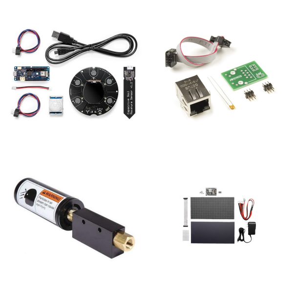
<h1> Maker/DIY, Educational </h1> <p> Maker/DIY and educational products include introductory self-study resources for the electronics field, such as user-assembled robotics kits and introductory texts, 3D printers and filaments for additive manufacturing of mechanical parts, reference texts for industry professionals, and (while they last) limited-supply vintage data books; emblems of an era when product information was transmitted in physical form that is rapidly fading into irretrievable memory. </p>
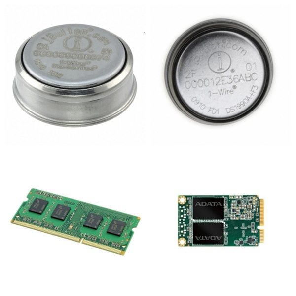
<h1> Memory - Modules, Cards </h1> <p> Memory - Modules, Cards mainly refer to integrated memory modules and memory card products, whose core function is to provide high-performance, high-density data storage solutions for various electronic devices. </p> <h2> 1. Overview </h2> <p> <strong>Memory Modules</strong> </p> <p> Usually, multiple memory chips (such as DRAM or SRAM) are integrated on a PCB substrate and connected to the main system through a standardized interface. For example, memory sticks (DIMM/SO-DIMM) belong to this category. Multiple DRAM chips form a super-cell array inside, and data addressing is achieved through row and column addresses (RAS/CAS). </p> <p> <strong>Memory Cards</strong> </p> <p> Including portable storage media such as CompactFlash and SD cards, using flash memory technology (such as NAND Flash) to achieve non-volatile data storage, suitable for mobile devices or embedded systems. </p> <h2> 2. What the Main Types of Memory Modules and Cards? </h2> <p> <strong>Dynamic Random Access Modules (DRAM Modules)</strong> </p> <p> Such as DDR4/DDR5 memory sticks, which increase the data transmission rate through synchronous clocks and are widely used in computer main memory. </p> <p> <strong>Static Random Access Modules (SRAM Modules)</strong> </p> <p> Applicable to high-speed cache scenarios, due to the low latency characteristics of the bistable circuit design, but the cost is relatively high. </p> <p> <strong>Specialized Memory Cards</strong> </p> <p> Such as the industrial-grade OMG-COMM8-PCI card, which supports specific protocols (such as CompactPCI) and is used in communication equipment or industrial control systems. </p> <h2> 3. Brands and Manufacturers for Memory Modules and Cards </h2> <p> <strong>Mainstream brands</strong> </p> <p> Kingston, Samsung, Micron, etc. provide standardized memory modules; Dataram, Meritec, and other manufacturers focus on customized storage solutions. </p> <p> <strong>Technical Features</strong> </p> <p> High-end modules use heat sink packaging (such as FBD-533 memory) and support ECC verification to improve data reliability. </p> <h2> 4. What are Memory Modules and Cards Used for? </h2> <p> <strong>Servers and Data Centers</strong> </p> <p> Large-capacity RDIMM/LRDIMM modules are used to increase server memory bandwidth and capacity. </p> <p> <strong>Embedded Systems</strong> </p> <p> Memory cards such as CompactFlash are suitable for IoT devices and industrial controllers due to their small size and low power consumption. </p> <p> <strong>Consumer Electronics</strong> </p> <p> DDR memory sticks and SD cards are widely used in terminal devices such as PCs and smartphones. </p> <p> The technological evolution direction of such products is higher density (such as 3D stacking technology), lower power consumption (LPDDR5), and higher speed interface (PCIe 5.0). </p> <h2> <strong>Memory Modules and Cards FAQs</strong> </h2> <h3> 1. How do you choose memory modules and cards? </h3> <p> <strong>Capacity</strong>: Choose according to the device requirements, for example, 4K/8K video shooting requires 128 GB and above. </p> <p> <strong>Speed level</strong>: Pay attention to the write speed (such as V30, V60) to ensure smooth HD video recording. </p> <p> <strong>Compatibility</strong>: Confirm the card types (such as SDXC and microSDXC) and maximum capacity limits supported by the device. </p> <h3> 2. What is the Relationship between memory cards and passive components? </h3> <p> The memory card is composed of NAND flash memory chips (passive components) and control circuits (active components) and is a hybrid electronic component. </p> <p> The core storage unit relies on semiconductor technology and meets the basic characteristics of integrated circuits (ICs). </p> <h3> 3. How to maintain memory modules and cards? </h3> <p> <strong>Formatting</strong>: Format in the device before first use to avoid compatibility issues. </p> <p> <strong>Data backup</strong>: Export content regularly to prevent data loss due to physical damage. </p> <p> <strong>Avoid extreme environments</strong>: High temperature, humidity or magnetic fields may affect the life of the memory card. </p>
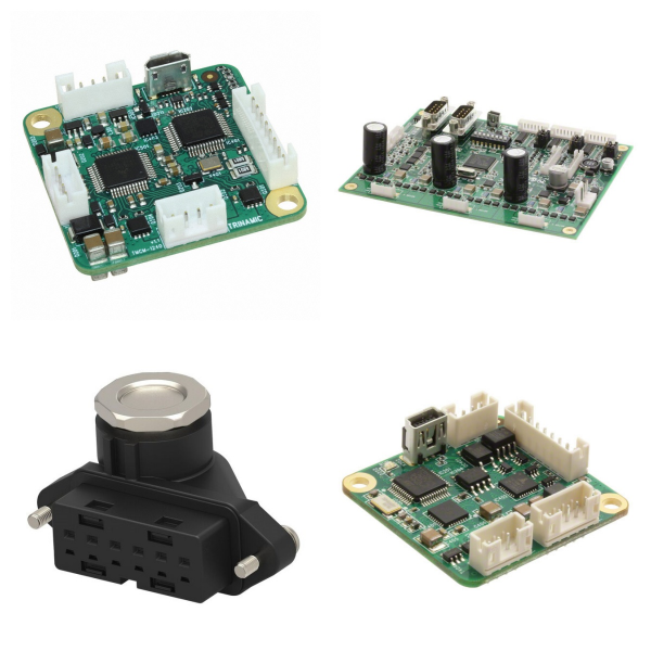
<h1> Motors, Actuators, Solenoids and Drivers </h1> <h2> 1. Core Components Overview </h2> <p> <strong>Motors</strong>: As the power source of mechanical systems, common types include DC motors and brushless motors. Portescap's 20DAM series digital linear actuators combine high linear force (up to 108 ounces) with low-cost design for precision control scenarios. </p> <p> <strong>Actuators</strong>: Responsible for converting electrical signals or energy into mechanical actions, they are widely used in industrial automation, aerospace and automotive fields. They include mechanical, electronic and electromagnetic types. </p> <p> <strong>Solenoids</strong>: A type of electromagnetic actuator that drives the core to move through the coil current. They are commonly used in valve control, switch devices, and automotive transmission systems. For example, Unick's transmission actuators include solenoid valves and valve assemblies for emission control systems. </p> <p> <strong>Drivers</strong>: Provide control signals and power output for motors and solenoids. Texas Instruments' (TI) motor driver solution solves the current fluctuation and efficiency problems in solenoid drive by optimizing the power architecture. </p> <h2> 2. What are Motors, Actuators, Solenoids and Drivers Used for? </h2> <p> <strong>Industrial Automation</strong>: The growing demand for high-density digital I/O modules drives controllers toward compact, low-heat designs to support the integration of more sensors and actuators. </p> <p> <strong>Automotive Systems</strong>: Solenoids and electromagnetic actuators are used for transmission control, fuel injection, etc. and need to withstand high temperatures and vibration environments. </p> <p> <strong>Medical Equipment</strong>: Portescap's motor technology is used in medical infusion systems, emphasizing high precision and reliability. </p> <h2> 3. What are the Technology Trends and Challenges of Motors, Actuators, Solenoids and Drivers? </h2> <p> <strong>Integrated Design</strong>: ADI Trinamic™ proposes an intelligent drive solution that improves actuator response speed and energy efficiency by integrating driver chips with edge computing capabilities. </p> <p> <strong>Drive Optimization</strong>: The inductance characteristics of the solenoid and the change in mechanical load require the driver to have dynamic current regulation capabilities. TI's solution reduces electromagnetic interference through adaptive algorithms. </p> <p> <strong>High-density Control</strong>: Industrial controllers need to process more digital I/O signals in a limited space, driving innovations in modular circuit design and heat dissipation technology. </p> <h2> 4. What is the Industry Development Direction of Motors, Actuators, Solenoids and Drivers? </h2> <p> <strong>Intelligent</strong>: Actuators and drivers gradually integrate real-time feedback and communication functions to support remote monitoring and predictive maintenance. </p> <p> <strong>Energy efficiency improvement</strong>: The popularization of brushless motors and low-power drivers helps industrial equipment reduce energy consumption. </p> <h2> Motors, Actuators, Solenoids and Drivers FAQs </h2> <h3> 1. How do you choose a suitable motor driver? </h3> <p> The following factors should be considered comprehensively: </p> <p> <strong>Motor Type</strong>: DC, stepper, or AC motors need to match the corresponding driver; </p> <p> <strong>Control Accuracy</strong>: For example, the stepper motor driver needs to support subdivision control; </p> <p> <strong>Power Requirement</strong>: Select according to the load current and voltage range; </p> <p> <strong>Integration Capability</strong>: Whether it supports the communication interface with the microcontroller or PLC. </p> <h3> 2. What is the relationship between the driver and the motor device? </h3> <p> The driver and the motor together constitute a complete drive system. The driver directly affects the performance of the device (such as energy consumption and quietness) by adjusting the power conversion efficiency, while the motor body determines the upper limit of the mechanical output. </p> <h3> 3. How does the high-density digital IO module optimize the controller design? </h3> <p> In industrial automation, high-density IO modules reduce the use of discrete components by integrating FET and signal conditioning circuits, thereby reducing the size and heat generation, and supporting digital signal processing with more channels. </p> <h3> 4. What are the common faults of motor drivers? </h3> <p> <strong>Overheating</strong>: caused by overload or poor heat dissipation; </p> <p> Abnormal Control Signal: such as pulse loss or unstable voltage; </p> <p> <strong>Interface Compatibility Issues</strong>: mismatch with the communication protocol of the microcontroller or sensor. </p> <h3> 5. What are the common communication interfaces between the driver and the microcontroller? </h3> <p> <strong>PWM Signal</strong>: control speed or position through pulse width modulation; </p> <p> <strong>UART/I2C</strong>: used for parameter configuration and status feedback; </p> <p> <strong>CAN Bus</strong>: suitable for industrial multi-node communication scenarios. </p> <h3> 6. What are the possible causes and solutions for actuator response delay? </h3> <p> <strong>Mechanical Jam</strong>: lubricate or replace worn parts; </p> <p> <strong>Drive Signal Delay</strong>: check the controller code logic or signal transmission path; </p> <p> <strong>Insufficient Power Supply</strong>: ensure that the supply voltage and current meet the load requirements. </p>

<h1> Networking Solutions </h1> <p> The Network Solutions product category includes devices used to establish information connections between devices, data sources, and data sinks. Included products include switches, hubs, and routers used to establish connections between numerous devices that communicate using similar protocols, media converters used to connect devices that communicate over different media (such as fiber optics and twisted pair copper conductors), and servers used to connect devices that communicate using protocols of varying complexity (such as RS232/422/485 to Ethernet or USB). </p>
<h1> Optical Inspection Equipment </h1> <p> Optical Inspection Equipment is key equipment in the production and inspection of electronic components. It uses optical imaging and algorithm technology to perform non-contact, high-precision defect detection and quality control on products. </p> <h2> 1. What is the Technical Principle of Optical Inspection Equipment? </h2> <p> Optical Imaging and Algorithm Analysis: Capture the surface image of the object to be tested through a high-resolution camera, combine multiple types of light sources (such as ring light, strip light, coaxial light) to highlight the detection features, and then use image processing algorithms to identify abnormalities such as size deviation, welding defects, and surface flaws. </p> <p> Multi-spectral Detection: Some equipment uses multi-band light sources or spectral analysis technology to detect deep characteristics such as material composition and coating uniformity. </p> <h2> 2. What are the Core Components of Optical Inspection Equipment? </h2> <p> Light Source System: Supports brightness and angle adjustment to meet the inspection needs of different materials (such as reflective/dark PCBs). For example, the AOI equipment of JEENOCE reduces interference by optimizing the light source. </p> <p> High-precision Camera: Industrial-grade cameras provide micron-level resolution and can capture fine structures such as solder joints and pins. </p> <p> Image processing system: Real-time analysis of image data, rapid location of defects (such as component offset, cold solder joints, scratches) , and classified alarms. </p> <h2> 3. What is the Optical Inspection Equipment Used for? </h2> <p> PCBA/SMT production: Detect component position, solder joint quality, and circuit connectivity in the SMT and soldering stages to ensure yield. </p> <p> Semiconductor manufacturing: Used for wafer surface defect detection, key dimension measurement (such as OCD technology), and film thickness analysis, supporting nanometer-level precision. </p> <p> Finished product inspection: Automatically complete the dimensional compliance, appearance integrity, and functional screening of electronic components, replacing manual visual inspection. </p> <h2> 4. What are the Advantages of Optical Inspection Equipment? </h2> <p> High efficiency and consistency: Fully automatic inspection speed far exceeds manual inspection, avoiding subjective errors, and suitable for large-scale production. </p> <p> Non-destructive: Compared with electron beam inspection, optical inspection does not damage samples and is suitable for online real-time monitoring. </p> <p> Multi-scenario adaptation: Through modular design (such as replacing light sources or lenses), it can be expanded to the inspection needs of different product lines. </p> <h2> 5. What are the Typical Types of Optical Inspection Equipment? </h2> <p> AOI (automatic optical inspection) equipment: dedicated to SMT/PCBA processes, such as the JEENOCE AOI with multi-light source coordination and high-speed image processing capabilities. </p> <p> OCD (optical critical dimension) equipment: used for line width and morphology measurement in semiconductor manufacturing, combined with computational optics to improve accuracy. </p> <p> One-button inspection equipment: integrated optical sensors and robotic arms to achieve full automation of inspection and sorting, suitable for standardized component production. </p> <p> Optical inspection equipment continues to improve the quality control level of electronic components through technological innovation and has become an indispensable part of modern electronic manufacturing. </p> <h2> 6. Optical Inspection Equipment FAQs </h2> <h3> 1) How to choose the right optical inspection equipment? </h3> <p> The following factors need to be considered comprehensively: </p> <p> Inspection Requirements: defect type (surface/internal), accuracy requirements (micrometer/nanometer level), throughput. </p> <p> Compatibility: whether the equipment supports different wafer sizes, packaging forms, and new materials (such as compound semiconductors). </p> <p> Software Functions: data analysis capabilities (such as AI defect classification), and integration with the factory MES system. </p> <h3> 2) What are the advantages of optical inspection equipment over traditional manual inspection? </h3> <p> Efficiency Improvement: automated scanning and analysis can quickly complete large-scale inspections and reduce manual operation time. </p> <p> Accuracy Assurance: high-resolution imaging technology (such as microscopes and high-resolution cameras) can identify micron-level defects and avoid human visual errors. </p> <p> Data Traceability: the inspection results are automatically reported and stored to facilitate process optimization and problem tracing. </p> <h3> 3) What challenges may optical inspection equipment encounter when inspecting electronic components? </h3> <p> Complex Surface Interference: Surface reflections and multi-layer structures of components may affect the imaging quality, requiring adjustment of the light source or algorithm optimization. </p> <p> Micro Defect Identification: Nano-scale defects (such as electrode microcracks) require higher-precision equipment (such as electron beam detection), and optical detection has resolution limitations. </p> <p> Material Compatibility: Some new materials (such as transparent substrates and flexible circuits) require customized optical parameters or detection solutions. </p> <h3> 4) How to better maintain optical inspection equipment? </h3> <p> Optical Component Cleaning: Clean the lens and filter regularly to prevent dust or stains from affecting the imaging quality. </p> <p> Calibration and Calibration: Periodically calibrate the light source intensity, focal length, and imaging system to ensure stable detection accuracy. </p> <p> Software Update: Upgrade the algorithm library to support the identification of new defect types or optimize the detection logic. </p>
<h1> Optics </h1> <p> Optics is the scientific term for the study of light. Optical products include lenses, light pipes, reflectors, and remote fluorescent light sources. These products all manipulate the light provided to them in some way. </p>
<h1> Optoelectronics </h1> <p> Optoelectronics is a field that crosses electronics and photonics. Its core function is to achieve information transmission, energy regulation, and signal processing through the mutual conversion of light and electricity. Its devices use the optoelectronics properties of semiconductor materials to convert electrical signals into optical signals or vice versa, and are widely used in communication, display, sensing and other fields. </p> <h2> 1. Optoelectronics Overview </h2> <p> Definition: Optoelectronics focuses on the interaction between light and electricity, covering light-emitting devices (such as LEDs, and lasers), light detection devices (such as photodiodes, and photoresistors), and light modulation devices (such as electro-optical modulators). </p> <p> Technical Basis: Mainly based on III-V compound semiconductors (such as GaAs, and InP), these materials have direct band gap characteristics and can efficiently achieve electroluminescence or photoconductivity effects. For example, by adjusting the band gap of semiconductor materials (such as 3.4eV of GaN), the device can be controlled to emit visible light or infrared light. </p> <h2> 2. What are the Main Types and Device Characteristics of Optoelectronics? </h2> <h3> 1)Light-emitting device: </h3> <p> LED: Converts electrical energy into light of a specific wavelength, used for lighting, display screens, etc. </p> <p> Laser: Generates highly coherent light beams, used in fiber-optic communications and medical equipment. </p> <h3> 2)Photodetector device: </h3> <p> Photodiode: Converts optical signals into electrical signals, has a fast response speed, and is suitable for optical communication receiving ends. </p> <p> Photoresistor: Changes resistance value based on light intensity, used in scenarios such as light-controlled switches. </p> <h3> 3)Optocoupler: </h3> <p> It consists of a light source (such as an infrared LED) and a light detector (such as a phototransistor), which realizes electrical isolation between input/output circuits and improves the system's anti-interference ability. </p> <h2> 3. What are the Key Parameters and Performance Indicators of Optoelectronics? </h2> <p> Wavelength range: Visible light (400-700nm), infrared light (>700nm), or ultraviolet light (<400nm), determined by the band gap of the semiconductor material. </p> <p> Response time: The speed at which optoelectronic devices convert light/electrical signals directly affects the performance of high-frequency applications (such as high-speed communications). </p> <p> Isolation voltage: The voltage resistance between the input and output ends of an optocoupler device, with a typical value of several thousand volts. </p> <p> Conversion efficiency: Such as the light efficiency (lm/W) of an LED or the photoelectric conversion efficiency of a solar cell. </p> <h2> 4. Where are Optoelectronics Used for? </h2> <p> Optical communication: Lasers and photodetectors in optical fiber communication systems are core components. </p> <p> Display technology: LED displays, LCD backlights, and OLED panels all rely on optoelectronic devices. </p> <p> Industrial control: Optocouplers are used in motor drives, power management, and other scenarios to ensure safe signal transmission. </p> <p> Medical and sensing: Photodetectors are used in medical equipment such as pulse oximeters and infrared thermometers. </p> <h2> 5. What are the Development Trends of Optoelectronics? </h2> <p> Optoelectronic devices are evolving towards miniaturization and high integration. For example, silicon-based optoelectronic technology (silicon photonics) integrates optical devices with CMOS circuits, driving innovations in data centers and 5G communications. In addition, new materials (such as perovskites) and quantum dot technologies are expanding the application potential of optoelectronic devices in flexible displays, high-efficiency photovoltaics, and other fields. </p> <h2> 6. Optoelectronics FAQs </h2> <h3> 1) What are the Core Application Areas of Optoelectronics? </h3> <p> Mainly includes optical communications, display technology (such as LCD and LED), optical sensors, laser technology, and light energy conversion equipment. </p> <h3> 2) What are the Typical Types of Optoelectronic Devices? </h3> <p> Mainly includes light sources (such as semiconductor lasers and LEDs), light detectors, light modulators (such as electro-optical crystals and liquid crystals), optical fibers, and display devices (such as LCD screens and plasma displays). </p> <h3> 3) What are the Common Defects of LCD Screens? </h3> <p> Narrow Viewing Angle: The vertical viewing angle is clear, and other angles are prone to smearing. </p> <p> Fragility: Due to the characteristics of the liquid crystal molecular structure, the physical impact resistance is weak. </p> <h3> 4) How do Optoelectronic Devices Achieve Energy Conversion? </h3> <p> Through the photoelectric effect of semiconductor materials, light energy is converted into electrical energy (such as solar cells), or electrical energy is converted into light energy (such as LED light emission). </p> <h3> 5) What are the Advantages of Optoelectronic Systems in Communications? </h3> <p> Compared with traditional electrical signal transmission, light wave carriers have higher bandwidth, anti-interference ability, and long-distance transmission efficiency. </p>
<h1> Potentiometers, Variable Resistors </h1> <h2> 1. Potentiometers and Variable Resistors Overview </h2> <p> <strong>Potentiometer</strong>: A resistor element with three terminals and adjustable resistance. The resistance value is changed by sliding contacts to achieve voltage division or current limiting functions. Its core principle is to change the length of the current path or the contact area by adjusting the contact position, thereby changing the output resistance. </p> <p> <strong>Variable Resistors</strong>: In a broad sense, it includes potentiometers, but in a narrow sense, it refers to variable resistors with only two effective terminals (such as fine-tuning resistors). The resistance value is changed by adjusting the mechanical structure, and it is often used for circuit calibration or debugging. </p> <h2> 2. What is the Structure and Working Principle of Potentiometers? </h2> <p> <strong>Structure</strong>: The potentiometer consists of a resistor element (such as carbon film, and wire-wound resistor) and a sliding contact. The two ends of the resistor element are fixed terminals, and the sliding end (brush) changes the contact point position by rotation or linear movement. </p> <p> <strong>Voltage division principle</strong>: The input voltage is applied to the two ends of the resistor element, and the voltage output between the sliding end and any fixed end is proportional to the contact position, realizing the voltage division function. </p> <h2> 3. What are the Common Types of Potentiometers? </h2> <h3> 1)By adjustment method: </h3> <p> <strong>Rotary potentiometer</strong>: Adjusted by knob, widely used in volume control, brightness adjustment, etc. </p> <p> <strong>Linear (sliding) potentiometer</strong>: Adjusted by linear sliding, suitable for scenarios requiring linear response (such as dimmers). </p> <p> <strong>Trimmer</strong>: Miniaturized design requires tool adjustment and is used for circuit debugging or calibration. </p> <h3> 2)By material and power: </h3> <p> <strong>Carbon film/ceramic film potentiometer</strong>: Low cost, suitable for low power scenarios. </p> <p> <strong>Wire wound potentiometer</strong>: High power, high precision, used for industrial control. </p> <h2> 4. What are Potentiometers Used for? </h2> <p> <strong>Voltage division and signal adjustment</strong>: Audio equipment volume control, sensor signal adjustment. </p> <p> <strong>Power control</strong>: Light dimmer, motor speed adjustment (pay attention to power limit). </p> <p> <strong>Calibration and debugging</strong>: Trimmer resistors are used for precise adjustment of circuit parameters (such as bias voltage). </p> <h2> 5. What are the Key Parameters of Potentiometers? </h2> <p> <strong>Resistance range</strong>: Commonly from a few hundred ohms to megohms, selected according to the application. </p> <p> <strong>Power rating</strong>: Determines the maximum power consumption that can be tolerated (such as 0.1W to 5W). </p> <p> <strong>Linearity</strong>: The corresponding relationship between the change in resistance and the movement of the contact, affects the control accuracy. </p> <p> <strong>Mechanical life</strong>: The number of rotations or slides (usually tens of thousands of times). </p> <h2> 6. What is the Special Function Design of Potentiometers? </h2> <p> <strong>Attached switch</strong>: Some potentiometers integrate power switches, which are common in volume control knobs (triggered off when the contact is adjusted to the minimum resistance value). </p> <p> <strong>Multi-gang potentiometer</strong>: Multiple resistance units are linked, used in stereo audio equipment. </p> <h2> 7. Typical Brands for Potentiometers </h2> <p> BOURNS </p> <p> VISHAY </p> <p> TE </p> <p> ALPHA </p> <p> Panasonic </p> <p> Amphenol </p> <h2> 8. Potentiometers FAQs </h2> <h3> 1) What is the difference between a potentiometer and a variable resistor? </h3> <p> <strong>Potentiometer</strong>: Usually used as a three-terminal component, it outputs a voltage proportional to the contact position through the voltage division principle. </p> <p> <strong>Variable Resistor</strong>: Generally used as a two-terminal component, it only limits the current by adjusting the resistance value and has no voltage division function. </p> <h3> 2) What are the advantages of digital potentiometers? </h3> <p> It can be adjusted by a microprocessor or digital signal to support automatic control. </p> <p> Some models integrate non-volatile memory to retain the settings after power failure. </p> <p> It is small and high in precision, suitable for highly integrated circuits. </p> <h3> 3) What are the common faults and detection methods of potentiometers? </h3> <p> <strong>Poor Contact</strong>: It is manifested as a jump in the output signal. A multimeter can be used to detect whether the resistance value changes continuously. </p> <p> <strong>Mechanical Wear</strong>: Noise occurs when rotating or sliding, and the potentiometer needs to be replaced. </p> <p> <strong>Detection Steps</strong>: Measure whether the total resistance of the two ends meets the nominal value, and check whether the resistance between the sliding end and the fixed end changes linearly with the adjustment. </p> <h3> 4) Which special potentiometers have additional functions? </h3> <p> <strong>Potentiometer with switch</strong>: The switch can be triggered when rotating or sliding to the extreme position, which is often used in the integrated design of power switches and volume adjustment (such as old radios). </p> <p> <strong>Multi-gang potentiometer</strong>: Multiple potentiometers share the same adjustment axis, which is used to synchronously control multiple signals (such as stereo audio balance adjustment). </p> <h3> 5) What role does the potentiometer play in analog-to-digital conversion? </h3> <p> In the analog signal acquisition system, the potentiometer can be used as a voltage divider to provide a reference voltage and cooperate with the analog-to-digital converter (ADC) to convert analog signals (such as position and brightness) into digital signals. </p> <h2> Summary </h2> <p> Potentiometers and variable resistors adjust resistance values mechanically or digitally. They are core components of analog circuit control and are widely used in consumer electronics, industrial equipment, and debugging scenarios. Their selection needs to comprehensively consider resistance range, power, accuracy, and usage environment. </p>
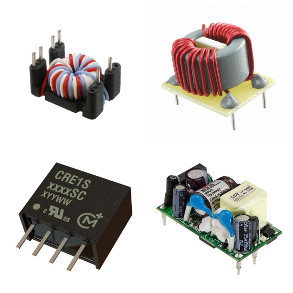
<h1> Power Supplies - Board Mount </h1> <h2> 1. Overview </h2> <h3> 1)Basic Concepts </h3> <p> “Power Supplies - Board Mount” refers to compact power modules that can be directly mounted on a printed circuit board (PCB), including AC/DC or DC/DC conversion functions, and are used to provide stable power for electronic devices. </p> <p> </p> <h3> 2)Main Types </h3> <p> <strong>Isolated Modules</strong>: The input and output ends are electrically isolated by a transformer, and the isolation voltage is usually 1.5kV-3kV, which is suitable for scenarios with high anti-interference requirements. </p> <p> <strong>Non-isolated Modules</strong>: Smaller and lower in cost, suitable for applications with limited space and no isolation. </p> <h2> 2. What are the Core Parameters and Features of Board Mounted Power? </h2> <h3> 1)Input/Output Range </h3> <p> <strong>Input Voltage</strong>: Covers a wide range of inputs, such as DC 0.7V-15V (low voltage scenario) or AC 90V-264V (universal AC input). </p> <p> <strong>Output Voltage</strong>: Supports single or multiple outputs, such as DC 1.8V, 5V, 12V, 500V, etc., to meet different load requirements. </p> <h3> 2)Power and Efficiency </h3> <p> The power range is from 4W (AC/DC module) to 120W (high-voltage DC/DC module), and the efficiency is generally higher than 85%, and some models can reach 88.5%. </p> <p> Adopt interleaved PFC (power factor correction) and PSFB (phase-shifted full-bridge) topology to improve energy efficiency. </p> <h3> 3)Safety and Certification </h3> <p> Complies with EN55022 Class B electromagnetic compatibility standard passes 3kV isolation voltage test and has overcurrent (OCP), overvoltage (OVP), and over temperature (OTP) protection functions. </p> <h2> 3. What is Board Mounted Power Used for? </h2> <p> <strong>Industrial control equipment</strong>: such as PLC and sensor power supply, which need to withstand wide temperature environment (-40 °C to 100 °C) and vibration conditions. </p> <p> <strong>Communication infrastructure</strong>: CRPS (common redundant power supply) architecture is used in servers and switches to support hot plugging and redundant backup. </p> <p> <strong>Medical and test instruments</strong>: Modules that rely on high isolation voltage and low noise output to ensure equipment safety and accuracy. </p> <h2> 4. How to Choose Board Mounted Power? </h2> <p> <strong>Load matching</strong>: Select a model with a power margin of ≥20% based on the device power consumption to avoid overload. </p> <p> <strong>Installation method</strong>: Give priority to standard packaging (such as 1/8 Brick size) and compatible with PCB layout requirements. </p> <p> <strong>Management interface</strong>: Some modules support PMBus/SMBus protocols to facilitate remote monitoring of power status. </p> <h2> 5. Board Mounted Power FAQs </h2> <h3> 1) Which components are prone to power failure? </h3> <p> <strong>Electrolytic Capacitors</strong>: Common failures include reduced capacity, leakage, or short circuits, which may cause unstable power output or complete failure. </p> <p> <strong>Resistors</strong>: Low-resistance resistors are easily burned due to overcurrent, and high-resistance resistors may drift due to aging, affecting the voltage division or current limiting function of the power supply. </p> <p> <strong>SMT Components</strong>: SMT components are small, and poor welding or thermal stress may cause contact failure. </p> <h3> 2) How to detect power supply-related component failures? </h3> <p> <strong>Capacitor Test</strong>: Use a multimeter to measure whether the capacity has decreased, or observe whether there is physical damage such as bulging or leakage. </p> <p> <strong>Resistance Test</strong>: Low-resistance resistors are easy to identify when they are burnt and blackened, and high-resistance resistors need to measure whether the resistance is abnormal. </p> <p> <strong>Short Circuit Troubleshooting</strong>: Use the adjustable power supply to gradually increase the pressure and observe the heating element to locate the short circuit point. </p> <h3> 3) What are the possible reasons for the abnormal output of the power module? </h3> <p> <strong>Capacitor Failure</strong>: The decrease in the capacity of the filter capacitor will cause the output voltage ripple to increase. </p> <p> <strong>Welding Problem</strong>: Cold welding or cold welding may cause poor contact, which may be good or bad. </p> <p> <strong>External Interference</strong>: Unshielded power lines may introduce noise, so grounding and shielding measures need to be checked. </p> <h3> 4) How to test the stability of power supply output? </h3> <p> <strong>Ripple Test</strong>: Use an oscilloscope to measure the AC component of the output voltage, which must meet the design specifications (such as <50mV). </p> <p> <strong>Load Regulation</strong>: Test the voltage fluctuation range under different loads. </p> <p> <strong>Transient Response</strong>: Observe the recovery time and overshoot voltage through step load changes. </p>
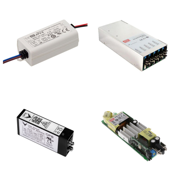
<h1> Power Supplies - External or Internal (Off-Board) </h1> <h2> 1. Overview </h2> <p> External power supply: refers to a power supply module independent of the device, such as an AC/DC wall adapter. Typical models include a 5V/15W AC-to-DC adapter, which has the characteristics of a wide input voltage range and stable output. </p> <p> Internal power supply: A power supply unit integrated inside the device, including a PCB onboard power module, which supports customized configuration to meet the power requirements of different devices. </p> <h2> 2. What are the Technical Features of Off-Board Power Supply? </h2> <p> Circuit Design: </p> <p> A secondary EMI filter circuit is used to reduce electromagnetic interference, and energy efficiency is improved through PFC (power factor correction) technology; </p> <p> Integrated high and low voltage conversion topology structure, with low voltage filter circuit to ensure output stability. </p> <p> Protection Function: </p> <p> Built-in overvoltage, overcurrent and short circuit protection mechanisms, such as a bidirectional current limiting chip that can achieve 28V withstand voltage and 6A current management; </p> <p> Some models support external adjustable soft start and overvoltage threshold settings to enhance system compatibility. </p> <h2> 3. What is Off-Board Power Supply Used for? </h2> <p> Consumer electronics: external adapters for portable devices such as laptops and tablets; </p> <p> Industrial equipment: uninterruptible power supplies (UPS) and docking stations for servers and industrial control systems; </p> <p> Communications: power management solutions for high-power transmission standards such as Thunderbolt/USB Type-C. </p> <p> This category of products balances versatility and customization through modular design, while taking into account safety certification (such as 3C) and heat dissipation optimization. </p>
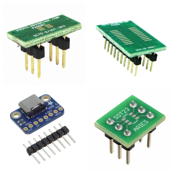
<h1> Prototyping, Fabrication Products </h1> <p> Prototyping and manufacturing products include materials and tools used to assemble small quantities of electronic circuits for development, research, repair, or similar purposes. Examples include solderless breadboards and adapters (for use with surface mount integrated circuits), perforated and non-perforated circuit board materials, and tools for producing printed circuit boards using chemical or mechanical processing techniques. </p>
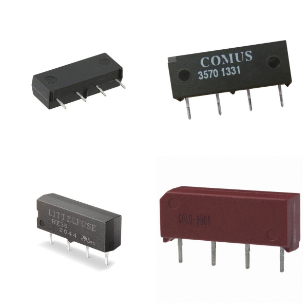
<h1> Relays </h1> <h1> 1. Relays Overview </h1> <p> Relays are electronic switching devices that control the on and off of output circuits through input signals. They can realize the functions of controlling large currents with small currents, isolating strong and weak currents, and switching circuits. Its core functions include automatic adjustment, safety protection, and signal conversion, and are widely used in power systems, automation control, communication equipment, and other fields. </p> <h2> 2. How Relays Work? </h2> <h3> 1) Structure Composition </h3> <p> Electromagnetic relay: It is composed of mechanical parts such as an iron core, coil, armature, and contact spring, and relies on electromagnetic effect to drive the contact action. </p> <p> Solid-state relay (SSR): It has no mechanical parts and consists of three parts: input circuit (control signal), drive circuit (photoelectric coupling or high-frequency transformer isolation), and output circuit (semiconductor devices such as thyristor, MOSFET, etc.). </p> <h3> 2) Working Principle </h3> <p> Electromagnetic type: When the coil is energized, a magnetic field is generated, which attracts the armature to drive the contacts to close or open, thereby realizing the on and off of the circuit. </p> <p> Solid-state type: The input control signal is isolated by a photocoupler and then triggers the output semiconductor device to switch the load circuit in a contactless manner. </p> <h2> 3. What are the Main Types of Relays? </h2> <h3> 1) Classification by load properties </h3> <p> AC relay: The output end uses a bidirectional thyristor (Triac), which is suitable for AC loads. </p> <p> DC relay: The output end uses MOSFET or IGBT to control DC loads. </p> <h3> 2) Classification by technical characteristics </h3> <p> Electromagnetic relay: Low cost, easy wear of contacts, suitable for low-frequency scenarios. </p> <p> Solid-state relay (SSR): No contacts, long life, fast response, suitable for high-frequency or high-reliability demand scenarios. </p> <p> Thermal reed relay: Utilizes the temperature control characteristics of magnetic materials, has a coil-free design, and is suitable for temperature-sensitive scenarios. </p> <h2> 4. What are Relays Used for? </h2> <p> Industrial automation: Control high-power equipment such as motors and heaters. </p> <p> Power system: Realize overload protection, remote control, and signal isolation. </p> <p> Automotive electronics: used for lighting control, battery management, and other modules. </p> <p> Smart home: integrated into temperature control and security systems to achieve weak current control of strong current. </p> <h2> 5. What are the Differences Between Electromagnetic Relay and SSR? </h2> <table> <tbody> <tr class="firstRow"> <td width="118" valign="top" style="padding: 0px 7px; border-width: 1px; border-color: windowtext; background: rgb(215, 215, 215);"> <p> Characteristics </p> </td> <td width="234" valign="top" style="padding: 0px 7px; border-width: 1px; border-color: windowtext; background: rgb(215, 215, 215);"> <p> Electromagnetic relay </p> </td> <td width="216" valign="top" style="padding: 0px 7px; border-width: 1px; border-color: windowtext; background: rgb(215, 215, 215);"> <p> Solid-state relay (SSR) </p> </td> </tr> <tr> <td width="118" valign="top" style="padding: 0px 7px; border-left-width: 1px; border-left-color: windowtext; border-right-width: 1px; border-right-color: windowtext; border-top: none; border-bottom-width: 1px; border-bottom-color: windowtext;"> <p> Contact life </p> </td> <td width="234" valign="top" style="padding: 0px 7px; border-left-width: 1px; border-left-color: windowtext; border-right-width: 1px; border-right-color: windowtext; border-top: none; border-bottom-width: 1px; border-bottom-color: windowtext;"> <p> About 10⁵~10⁶ times (mechanical wear limit) </p> </td> <td width="216" valign="top" style="padding: 0px 7px; border-left-width: 1px; border-left-color: windowtext; border-right-width: 1px; border-right-color: windowtext; border-top: none; border-bottom-width: 1px; border-bottom-color: windowtext;"> <p> 10⁷~10⁸ times (contactless design) </p> </td> </tr> <tr> <td width="118" valign="top" style="padding: 0px 7px; border-left-width: 1px; border-left-color: windowtext; border-right-width: 1px; border-right-color: windowtext; border-top: none; border-bottom-width: 1px; border-bottom-color: windowtext;"> <p> Response speed </p> </td> <td width="234" valign="top" style="padding: 0px 7px; border-left-width: 1px; border-left-color: windowtext; border-right-width: 1px; border-right-color: windowtext; border-top: none; border-bottom-width: 1px; border-bottom-color: windowtext;"> <p> Millisecond level (mechanical action delay) </p> </td> <td width="216" valign="top" style="padding: 0px 7px; border-left-width: 1px; border-left-color: windowtext; border-right-width: 1px; border-right-color: windowtext; border-top: none; border-bottom-width: 1px; border-bottom-color: windowtext;"> <p> Microsecond level (semiconductor device response) </p> </td> </tr> <tr> <td width="118" valign="top" style="padding: 0px 7px; border-left-width: 1px; border-left-color: windowtext; border-right-width: 1px; border-right-color: windowtext; border-top: none; border-bottom-width: 1px; border-bottom-color: windowtext;"> <p> Isolation method </p> </td> <td width="234" valign="top" style="padding: 0px 7px; border-left-width: 1px; border-left-color: windowtext; border-right-width: 1px; border-right-color: windowtext; border-top: none; border-bottom-width: 1px; border-bottom-color: windowtext;"> <p> Electromagnetic isolation </p> </td> <td width="216" valign="top" style="padding: 0px 7px; border-left-width: 1px; border-left-color: windowtext; border-right-width: 1px; border-right-color: windowtext; border-top: none; border-bottom-width: 1px; border-bottom-color: windowtext;"> <p> Photoelectric/high-frequency transformer isolation </p> </td> </tr> <tr> <td width="118" valign="top" style="padding: 0px 7px; border-left-width: 1px; border-left-color: windowtext; border-right-width: 1px; border-right-color: windowtext; border-top: none; border-bottom-width: 1px; border-bottom-color: windowtext;"> <p> Anti-interference ability </p> </td> <td width="234" valign="top" style="padding: 0px 7px; border-left-width: 1px; border-left-color: windowtext; border-right-width: 1px; border-right-color: windowtext; border-top: none; border-bottom-width: 1px; border-bottom-color: windowtext;"> <p> Weak (susceptible to arc) </p> </td> <td width="216" valign="top" style="padding: 0px 7px; border-left-width: 1px; border-left-color: windowtext; border-right-width: 1px; border-right-color: windowtext; border-top: none; border-bottom-width: 1px; border-bottom-color: windowtext;"> <p> Strong (no spark interference) </p> </td> </tr> </tbody> </table> <h2> 6. Typical Parameter Examples of Relays </h2> <p> Take model 34.51.7.012.0010 as an example: </p> <p> √Coil voltage: 12VDC </p> <p> √Contact capacity: 6A/400VAC (SPDT type) </p> <p> √Response time: 5ms for pull-in, 3ms for release </p> <p> √Working temperature: -40 °C ~ 85 °C. </p> <h2> 7. How to Choose Relays? </h2> <p> Load Type: Prioritize matching of AC/DC load characteristics. </p> <p> Environmental Conditions: Solid-state relays are preferred in high-temperature or vibration scenarios. </p> <p> Life Requirements: Contactless SSRs are required for high-frequency operation. </p> <h2> 8. Typical Brands for Relays </h2> <p> Panasonic </p> <p> Omron relay </p> <p> Schneider </p> <p> HongFa </p> <p> SIEMENS </p> <p> CHNT </p> <h2> 9. Relays FAQs </h2> <h3> 1) What is the Difference between Relay and Contactor? </h3> <p> Relay: Suitable for low power control (usually ≤10A), small size, mostly used in electronic circuits. </p> <p> Contactor: Designed for high current (tens to hundreds of amperes), commonly used in industrial motor control. </p> <h3> 2) What are the Features of the Safety Relay? </h3> <p> Larger in appearance, modular design, mostly red/yellow. </p> <p> Adopt safety designs such as forced rail contacts to avoid failure caused by contact welding. </p> <h3> 3) How to Choose the Coil Voltage? </h3> <p> Need to match the rated voltage range to avoid too high (damage to the coil at high temperature) or too low (cannot work properly). The magnetic latching relay needs to ensure that the excitation pulse width is sufficient to prevent entering the neutral state. </p> <h3> 4) How to Suppress the Reverse Peak Voltage When the Coil is Powered Off? </h3> <p> Use transient suppression diodes or resistors, but it will extend the release time; if sensitive to the release time, you can balance it with a series resistor. </p> <h3> 5) What is the Effect of Contact Material on the Load? </h3> <p> AgNi+gold Plating: Suitable for small loads (such as signal relays). </p> <p> AgSnO₂: Suitable for inductive/capacitive loads (inrush current can reach 120A). </p>
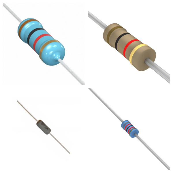
<h1> Resistors </h1> <h2> 1. Resistors Overview </h2> <h3> 1)Basic Concepts </h3> <p> The resistor is a passive component used to limit the flow of current in a circuit. It realizes the current limiting function by converting electrical energy into heat energy and is an energy-consuming component. Its resistance is determined by factors such as material, temperature, length, and cross-sectional area. </p> <h3> 2)Core Function </h3> <p> Voltage division and current division: Ensure stable operation of various parts of the circuit by adjusting voltage or current distribution. </p> <p> Current limiting and protection: Prevent current overload from damaging sensitive components. </p> <h2> 2. What are the Types of Resistors? </h2> <h3> 1)Classification by resistance characteristics </h3> <p> <strong>Fixed resistors</strong>: The resistance value cannot be adjusted, suitable for stable circuit design. </p> <p> <strong>Adjustable resistors</strong>: Such as potentiometers, which change the resistance value by sliding contacts and are used to accurately adjust circuit parameters. </p> <h3> 2)Classification by materials and processes </h3> <p> <strong>Wire-wound resistors</strong>: High precision, high-temperature resistance, suitable for high-power scenarios. </p> <p> <strong>Metal film/carbon film resistors</strong>: Low cost, low noise, widely used in general circuits. </p> <p> <strong>Chip resistor</strong>: Surface mount technology (SMT), small size, suitable for automated production. </p> <h3> 3)Special function resistor </h3> <p> <strong>Thermistor</strong>: Resistance changes with temperature, used for temperature sensing. </p> <p> <strong>Varistor</strong>: Voltage-sensitive, used for overvoltage protection. </p> <p> <strong>Photoresistor</strong>: Light intensity controls resistance, used in light control equipment. </p> <h2> 3. What are the Key Parameters of Resistors? </h2> <p> <strong>Resistance (Ω)</strong>: The Unit is ohm, marked by a color ring (plug-in resistor) or digital code (chip resistor). </p> <p> <strong>Power (W)</strong>: Maximum power that the resistor can withstand, which needs to match the circuit requirements to avoid overheating. </p> <p> <strong>Temperature coefficient</strong>: Measures the stability of resistance with temperature changes, and low-temperature coefficient is suitable for precision circuits. </p> <h2> 4. What are Resistors Used for? </h2> <p> <strong>General circuit</strong>: Basic functions such as voltage division, current limiting, and filtering. </p> <p> <strong>Precision instruments</strong>: Such as medical equipment and communication systems, which rely on high-precision resistors to ensure signal stability. </p> <p> <strong>Protection circuit</strong>: Varistors are used for lightning protection, and thermistors are used for overheating protection. </p> <p> <strong>Sensors</strong>: Photosensitive and thermistors play a key role in environmental monitoring. </p> <h2> 5. What is the Industrial chain and production of Resistors? </h2> <p> <strong>Production process</strong>: including thick film/thin film technology (chip resistors), winding process (high-power resistors), etc. </p> <p> <strong>Major manufacturers</strong>: such as Yageo and Fenghua Hi-Tech, occupy an important share of the global passive component market. </p> <h2> 6. Resistors FAQs </h2> <h3> 1) How to calculate the total resistance of resistors in series and parallel? </h3> <p> <strong>Series</strong>: The total resistance is equal to the sum of the resistances of each resistor, that is, Rtotal=R1+R2+⋯+Rn. </p> <p> <strong>Parallel</strong>: The reciprocal of the total resistance is equal to the sum of the reciprocals of each resistor, that is, Rtotal/1=R1 /1+R2/1+⋯+Rn/1. </p> <h3> 2) Can chip resistors be used above the rated temperature? </h3> <p> It is not recommended to use it above the rated temperature for a long time, which may cause performance degradation or damage. Please refer to the manufacturer's technical documents to evaluate the use conditions. </p> <h3> 3) What are the main functions of resistors in circuits? </h3> <p> Limiting current, voltage division, protecting sensitive components (such as LEDs), signal conditioning, etc. </p> <h3> 4)How to choose the rated power of resistors? </h3> <p> It needs to be selected based on the actual power consumption (P=I2R), ensuring that the rated power is greater than the actual power to avoid overheating failure while considering the influence of ambient temperature. </p> <h3> 5) Why must resistors be connected in series in LED circuits? </h3> <p> Current limiting is used to prevent LEDs from burning out due to excessive current. In typical applications, the resistance value needs to be calculated based on the LED voltage and the power supply voltage. </p> <h2> 6) What are the failure modes of resistors? </h2> <p> Common failures include overheating, resistance drift (caused by temperature or aging), and mechanical damage (such as package cracking). </p> <h2> 7. Summary </h2> <p> Resistors, as the basic components of electronic circuits, have a variety of types and parameter designs that meet a wide range of needs from consumer electronics to industrial equipment. </p> <p> In the future, with the trend of intelligence and precision, high reliability, miniaturization, and functional integration will become the core direction of the development of resistor technology. </p>
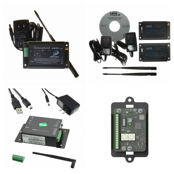
<h1> RF and Wireless </h1> <h2> 1. Radio Frequency (RF) Overview </h2> <p> <strong>1) Definition and Frequency Band</strong>: Radio Frequency refers to electromagnetic waves in the 300kHz-300GHz frequency band, which has high-frequency alternating characteristics and is the basic carrier of wireless signal transmission. </p> <p> <strong>2) Key Components</strong>: </p> <p> <strong>Passive devices</strong>: including inductors, capacitors, directional couplers and waveguides, etc., are used for signal matching, filtering, and power distribution. </p> <p> <strong>Active devices</strong>: such as microwave power amplifiers, diodes, and transistors, which undertake signal amplification, modulation, and demodulation functions. </p> <p> <strong>Connector</strong>: RF connectors (such as SMA and BNC) are used as electrical interfaces of transmission lines to ensure low-loss transmission of high-frequency signals. </p> <h2> 2. What is the Classification of Wireless Communication Technologies? </h2> <h3> 1)Short-Range Communication </h3> <p> <strong>Bluetooth</strong>: Based on the IEEE 802.15.1 standard, it uses the 2.4GHz ISM frequency band and a master-slave structure, which is suitable for low-power device interconnection. </p> <p> <strong>Wi-F</strong><strong>i</strong>: Follows IEEE 802.11 protocol, supports 2.4GHz/5GHz frequency bands, provides high-speed LAN access, and requires optimization of microstrip or coplanar waveguide transmission line impedance during design. </p> <p> <strong>RF</strong>: Such as 315MHz/433MHz frequency bands, used for remote controls and access control systems, with low transmission rates but low costs and complexity. </p> <h3> 2)Wide Area Communications </h3> <p> <strong>Mobile Network (4G/5G)</strong>: Integrates cellular technology and WLAN to achieve high-bandwidth, low-latency data transmission. </p> <p> <strong>LPWAN technology</strong>: Such as NB-IoT, designed specifically for the Internet of Things, covering long-distance, low-power scenarios. </p> <h2> 3. What is RF and Wireless Used for? </h2> <p> <strong>RF Module</strong>: Integrates high-frequency transceiver circuits, supports 1M-2Mbps rates, and is used in vehicle monitoring, industrial data collection, and smart homes. </p> <p> <strong>Antenna design</strong>: It is necessary to consider PCB stacking (such as L2 as RF reference ground in the four-layer board), routing continuity to avoid signal reflection, and matching network optimization (such as parallel capacitors and series inductors) to improve efficiency. </p> <h2> 4. How to Evaluate RF and Wireless? </h2> <p> <strong>Performance indicators</strong>: Including transmission power, frequency error, adjacent channel leakage ratio (ACLR) and receiving sensitivity, etc., which need to be tested by conduction and radiation methods. </p> <p> <strong>International certification</strong>: Such as FCC (USA), CE (EU), and TELEC (Japan), to ensure that the equipment complies with electromagnetic compatibility and RF specifications. </p> <h2> 5. What is the Development Trend of RF and Wireless? </h2> <p> <strong>High frequency</strong>: Expand to millimeter wave (30-300GHz) to meet 5G/6G requirements. </p> <p> <strong>Integration</strong>: SOC (system on chip) integrates RF front-end and baseband processing to reduce power consumption and volume. </p>
<h1> Sensors, Transducers </h1> <h2> 1. Overview </h2> <p> <strong>Sensors</strong> </p> <p> A detection device that can sense the measured information and convert it into electrical signals or other usable forms according to specific rules to meet the needs of information transmission, processing, storage, and control. Its core consists of sensitive elements (sense the measured quantity) and conversion elements (converted into electrical parameters). </p> <p> <strong>Transducers</strong> </p> <p> Broadly speaking, it refers to a device that converts energy or signals from one form to another. In the field of electronics, it often refers to a device that converts non-electrical quantities (such as temperature and pressure) into electrical signals, which partially overlap with the functions of sensors. </p> <h2> 2. What are the Core Characteristics and Classification of Sensors and Transducers? </h2> <h3> 1)Technical Features </h3> <p> <strong>Sensors</strong>: miniaturized, digital, intelligent, and with high sensitivity and resolution. </p> <p> <strong>Transducers</strong>: emphasize the conversion efficiency and accuracy of the signal form, such as converting mechanical vibration into a voltage signal. </p> <h3> 2)Classification Method </h3> <p> <strong>By energy form</strong>: physical type (such as light, heat), chemical type (such as gas), biological type (such as enzyme sensor) </p> <p> <strong>By technical principle</strong>: resistive, capacitive, piezoelectric, etc. </p> <p> <strong>By application scenario</strong>: industrial control, environmental monitoring, medical equipment, etc. </p> <h2> 3. Technology development and typical applications of Sensors and Transducers </h2> <h3> 1)Technology evolution </h3> <p> In the early days, structural sensors were the main type (such as resistance strain gauges); </p> <p> Solid-state sensors emerged after the 1970s and semiconductor materials were used to improve performance; </p> <p> MEMS (micro-electromechanical system) technology promoted the miniaturization and integration of sensors, such as the acceleration sensor of automobile airbags. </p> <h3> 2)Typical application scenarios </h3> <p> <strong>Industrial automation</strong>: pressure sensors are used for process control, and photoelectric sensors realize object detection. </p> <p> <strong>Consumer electronics</strong>: gyroscopes (MEMS) and temperature and humidity sensors in smartphones. </p> <p> <strong>Internet of Things (IoT)</strong>: Environmental monitoring nodes rely on a variety of sensors and wireless transmission converters. </p> <h2> 4. What are the Industry Trends of Sensors and Transducers? </h2> <p> <strong>Intelligent integration</strong>: sensors combined with AI to achieve edge computing and adaptive calibration. </p> <p> <strong>Application of new materials</strong>: such as aluminum nitride sensors can work stably in high-temperature (900 °C) environments. </p> <p> <strong>Interdisciplinary integration</strong>: MEMS technology combines microelectronics and mechanical processing to give rise to new sensing systems. </p> <h2> 5. Typical Brands for Sensors and Transducers </h2> <p> Omron </p> <p> VISHAY </p> <p> TI </p> <p> SICK </p> <p> BOURNS </p> <p> YAGEO </p> <p> Onsemi </p> <p> Molex </p> <p> ALLEGRO </p> <h2> 6. Sensors FAQs </h2> <h3> 1) How to calibrate the output signal of the sensor? </h3> <p> Calibration needs to be based on the standard reference value of the physical quantity and is achieved by adjusting the measuring resistance (RM/RB) or configuring the gain parameters of the ASIC chip to ensure that the output signal corresponds linearly to the input quantity. </p> <h3> 2) What environmental interference should be paid attention to when installing the sensor? </h3> <p> Strong magnetic fields and high-frequency noise sources (such as motors and inverters) should be avoided, and mechanical vibration and temperature fluctuations should be ensured to be within the allowable range of the sensor. </p> <h3> 3) How to deal with the zero drift problem of the sensor? </h3> <p> Zero drift may be caused by temperature changes or long-term use. Noise can be suppressed by regular calibration, selecting temperature-compensated sensors, or adding filtering circuits. </p> <h3> 4) Does the sensor output signal need to be amplified? How to choose an amplifier? </h3> <p> When the sensor output signal is weak (such as mV level), it needs to be matched with a high-precision operational amplifier (Op-Amp). When selecting, attention should be paid to bandwidth, noise figure, and common mode rejection ratio (CMRR). </p> <h3> 5) How to convert analog sensor signals into digital signals? </h3> <p> An analog-to-digital converter (ADC) can be used, and the resolution must match the sensor accuracy (such as 12-bit or 16-bit ADC), and communicate with the microcontroller through the SPI/I²C interface. </p> <h3> 6) How to ensure sensor safety in high voltage environment? </h3> <p> Select sensors with insulation that withstand voltage levels that meet the requirements (such as isolated Hall sensors), and design sufficient creepage distance and electrical clearance. </p> <h3> 7) How to ensure the performance of sensors under extreme temperatures? </h3> <p> Select wide temperature sensors (such as -40°C to 125°C), and avoid the core material from decreasing magnetic permeability due to temperature changes. </p> <h3> 8) How to determine whether the sensor is damaged? </h3> <p> <strong>Detection methods include</strong>: measuring whether the power supply voltage is normal, whether the output signal is within the theoretical range, and observing whether the linearity is abnormal. </p> <h3> 9) What should I do if the performance of the sensor deteriorates after long-term non-use? </h3> <p> It may be caused by material aging or residual magnetism of the core, and a recalibration or demagnetization operation is required to restore the core to its original state. </p> <h3> 10) How to choose pressure sensors in industrial automation? </h3> <p> The selection should be based on the medium type (liquid/gas), pressure range (such as 0-10MPa), and output type (analog/digital). Stainless steel housing and corrosion-resistant design are preferred. </p> <h3> 11) What sensors are commonly used in smart homes? </h3> <p> Including temperature and humidity sensors (such as NTC thermistors), human infrared sensors (PIR), and air quality sensors (such as PM2.5 detection modules). </p>
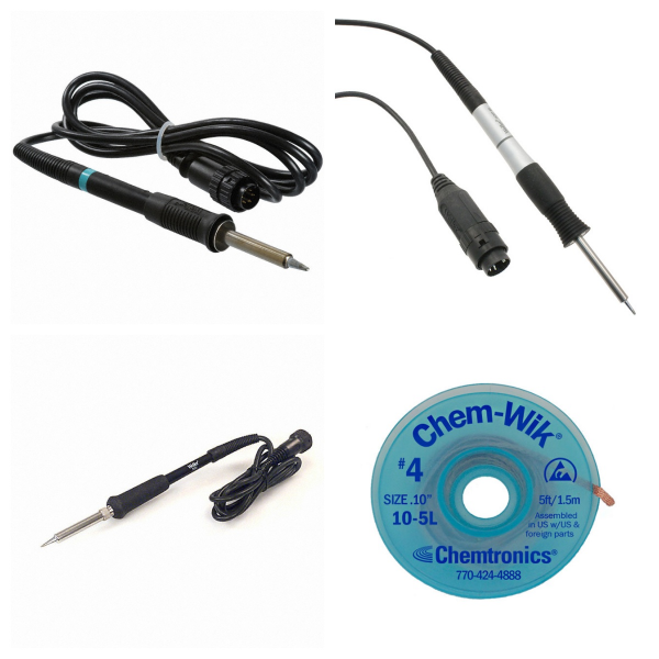
<h1> Soldering, Desoldering, Rework Products </h1> <p> Soldering, desoldering and rework products include tools and supplies generally used to make or remove electrical and mechanical connections between electronic components and the conductors used to interconnect them, whether those connections are discrete wire connections or printed circuit board traces. Examples of included products include solder in wire, paste or strip form, flux, soldering irons and pencils, hot air soldering irons, desoldering tools, and various replacement tips and accessories used to maintain or adjust such tools to accomplish specific tasks. </p>
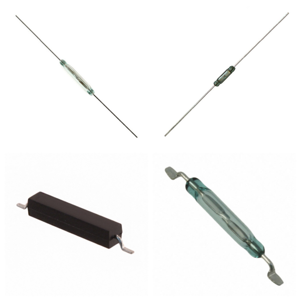
<h1> Switches </h1> <p> As a basic component, switches assume key control functions in communications, electronic equipment, and complex systems, and their technical forms continue to evolve with application needs. </p> <h2> 1. Switches Overview </h2> <p> <strong>Basic function</strong>: Control the conduction and disconnection of current by mechanical or electronic means to realize the opening and closing of circuits or path switching. </p> <p> <strong>Technical characteristics</strong>: Its actions only focus on the circuit connection status and do not involve the transmission content itself. For example, traditional telephone switches establish communication links through physical switches and disconnect them immediately after completion. </p> <h2> 2. What are Switches Used for? </h2> <p> <strong>Communication system</strong> </p> <p> Circuit switching networks (such as traditional telephone networks) rely on switches to achieve real-time connections between users and complete signal transmission through trunk lines. </p> <p> Although modern packet-switching technology uses similar physical architectures, it uses different protocols and switch types. </p> <p> <strong>Electronic device control</strong> </p> <p> Commonly found in circuit boards, used for power management, signal switching, and other functions, such as mechanical key switches or electronic MOSFET switches. </p> <h2> 3. What are the Related Components of Switches? </h2> <p> <strong>Relays</strong>: Use electromagnetic principles to control the on and off of high-power circuits, suitable for scenarios where strong/weak currents need to be isolated. </p> <p> <strong>Connectors</strong>: Used in conjunction with switches to ensure the reliability of physical connections between circuit modules. </p> <h2> 4. What is the Technological evolution of Switches? </h2> <p> In the early days, pure mechanical structures (such as toggle switches) were used and gradually developed into integrated electronic components (such as optocoupler isolation switches). </p> <p> Specialized switching devices (such as PCIe Switch) have been derived in the field of high-performance computing to expand data transmission channels, but their essence is still based on on-off control logic. </p> <h2> 5. Typical Brands for Switches </h2> <p> Schneider </p> <p> Siemens </p> <p> Omron </p> <p> Phoenix </p> <p> MOSO </p> <h2> 6. Switches FAQs </h2> <h3> 1) What are the Common Types of Switches? </h3> <p> <strong>Mechanical</strong>: touch switch, relay, etc., which control on and off through physical contacts; </p> <p> <strong>Semiconductor</strong>: MOS tube (divided into N-channel/P-channel), thyristor, etc., which use electric field effect to realize contactless switch. </p> <h3> 2) How to Choose the Core Parameters of MOS Tube as a Switch? </h3> <p> <strong>Vᴅss (maximum drain-source voltage)</strong>: needs to be higher than the actual working voltage and leave a 20% margin; </p> <p> <strong>Vɢs (gate-source voltage)</strong>: controls the conduction threshold and needs to match the driving circuit level. </p> <h3> 3) How to Determine the Polarity of MOS Tube? </h3> <p> <strong>Parasitic Diode Direction</strong>: The N-channel points from S pole to D pole, and the P-channel is the opposite; </p> <p> <strong>Channel Type Determination</strong>: the symbol arrow points inward for the N-channel, and vice versa for the P-channel. </p> <h3> 4) What are the Advantages of Semiconductor Switches in High-frequency Circuits? </h3> <p> MOS tubes and other semiconductor switches have no mechanical contacts and fast response speed (nanosecond level), which are suitable for high-frequency signal switching and PWM voltage regulation scenarios. </p> <h3> 5) How to Use Switches to Achieve Digital Circuit Logic Control? </h3> <p> By combining mechanical switches with logic gates (such as AND gates and OR gates), simple logic functions can be constructed, such as using a dip switch to set the input level and control the LED display status. </p> <h3> 6) What are the Characteristics of Thyristor (SCR) as a Switch? </h3> <p> A Thyristor is a semi-controlled semiconductor switch. After being triggered, it remains on until the current returns to zero. It is often used in AC voltage regulation, motor control, and other scenarios that require continuous conduction. </p>
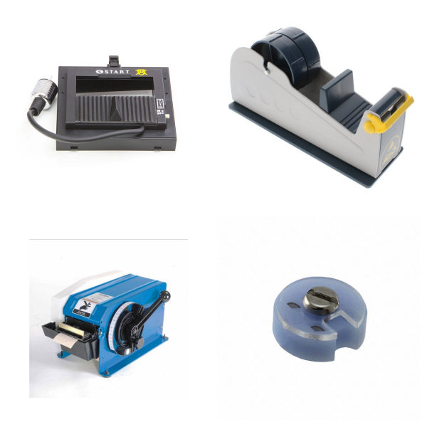
<h1> Tapes, Adhesives, Materials </h1> <p> Products in this category include tapes, adhesives, and material products other than those used for thermal interface or RF shielding applications. In addition to single-layer graphene, specular reflective films, hot melt adhesives, potting adhesives, and similar products, there are dozens of tapes: adhesive transfer tapes, anti-static tapes, barricade tapes, duct tapes, electrical tapes, flame retardant tapes, magnetic tapes, reflective tapes, ventilation tapes, and more. </p>
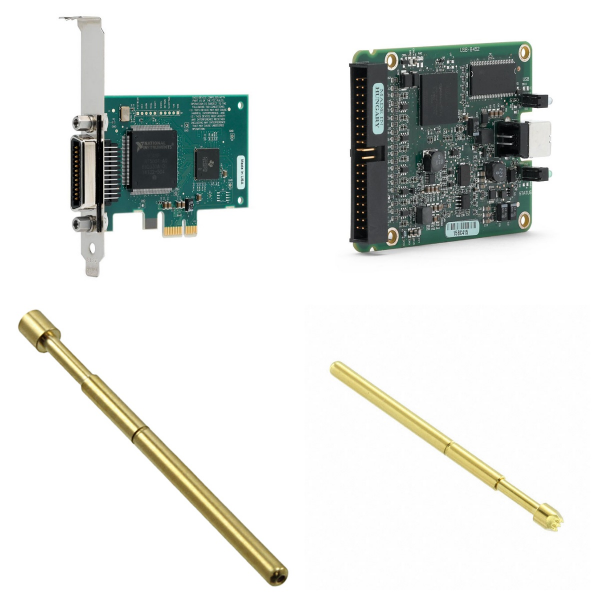
<h1> Test and Measurement </h1> <p> Test and measurement products include instruments, probes, and related equipment used to measure electrical and environmental quantities for development, diagnostics, quality control, or monitoring purposes. Examples include oscilloscopes, multimeters, test bench power supplies, thermocouple probes, alligator clips and banana test leads, function generators, as well as barometers, data loggers, sound level meters, thermal imagers, etc. </p>
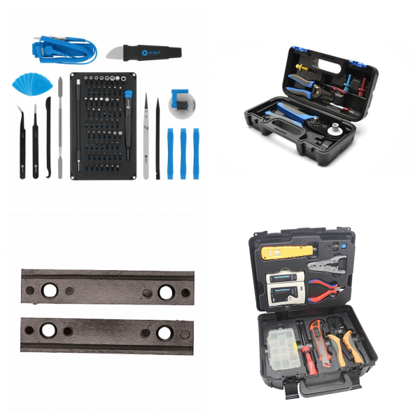
<h1> Tools </h1> <p> Tool products include general-purpose hand and power tools such as screwdrivers, nut drivers, socket drivers, wrenches, wire cutters, vacuum cleaners and flashlights, as well as specialty tools such as hand and machine-driven crimping tools for connector applications, insertion and extraction tools for various connector styles, fiber splicing and termination tools, and more. </p>
<h1> Transformers </h1> <p> Transformers specifically refer to transformers, whose core function is to achieve efficient conversion and transmission of electrical energy through the principle of electromagnetic induction. As the core device for power conversion, its design and application run through the entire chain of power, electronics, and communication systems, and are key components supporting the development of modern energy and information industries. </p> <p> </p> <h2> 1. Transformers Overview </h2> <p> A transformer is a magnetic component that uses the principle of electromagnetic induction to change AC voltage, current or impedance. Its working principle is based on Faraday's law of electromagnetic induction: when AC is passed into the primary winding, the alternating magnetic field generated will induce an electromotive force in the secondary winding, thereby realizing energy transfer. The voltage conversion ratio is determined by the turn ratio of the primary and secondary windings. </p> <p> </p> <h2> 2. What is the Core Structure and Classification of Transformers? </h2> <p> 1) Basic Structure: It consists of an iron core (magnetic core), a primary coil (primary winding), and a secondary coil (secondary winding). Some types use oil-immersed or dry designs to improve insulation and heat dissipation performance. </p> <p> </p> <p> 2) Classification standards: </p> <p> Purpose: distribution transformer, combination transformer, network transformer, etc. </p> <p> </p> <p> Construction: high-frequency transformer, pulse transformer, isolation transformer, etc. </p> <p> </p> <p> Cooling method: oil-cooled, air-cooled, etc. </p> <p> </p> <h2> 3. What are the Main Functions and Application Areas of Transformers? </h2> <p> 1) Function: </p> <p> Voltage/current conversion: matching the power requirements of different devices; </p> <p> </p> <p> Impedance matching: optimizing signal transmission efficiency; </p> <p> </p> <p> Electrical isolation: ensuring circuit safety. </p> <p> </p> <p> 2) Application scenarios: </p> <p> Power system: voltage rise and fall and power distribution in the power grid; </p> <p> </p> <p> Electronic equipment: power adapter, signal isolation, RF module power supply, etc. </p> <p> </p> <p> Communication network: network transformer realizes signal format conversion and noise isolation. </p> <p> </p> <h2> 4. What is the Technology Development Trend of Transformers? </h2> <p> Modern transformers are evolving towards high frequency, miniaturization, and integration, such as using new magnetic materials (such as amorphous alloys) to reduce losses or combining semiconductor technology to develop smart transformers. In addition, the demand for high-efficiency transformers in new energy fields (such as photovoltaic inverters and electric vehicle charging systems) continues to grow. </p> <p> </p> <h2> 5. Typical Brands for Transformers </h2> <p> YAGEO </p> <p> TDK </p> <p> BOURNS </p> <p> SIEMENS </p> <p> </p> <h2> 6. Transformers FAQs </h2> <h3> 1) What are the common types of transformers in electronic circuits? </h3> <p> Power transformer: used for AC voltage conversion (such as 220V to 12V); </p> <p> </p> <p> RF transformer: processes high-frequency signals and is often used in communication equipment; </p> <p> </p> <p> Audio transformer: optimizes the quality of audio signal transmission; </p> <p> </p> <p> Pulse transformer: used for pulse signal isolation in digital circuits. </p> <p> </p> <h3> 2) What parameters should be considered when selecting a transformer? </h3> <p> Input/output voltage: needs to match circuit requirements; </p> <p> </p> <p> Rated power: determines load capacity; </p> <p> </p> <p> Operating frequency: special types (such as RF transformers) are required for high-frequency circuits; </p> <p> </p> <p> Packaging form: selected according to space and heat dissipation requirements. </p> <p> </p> <h3> 3) What is the difference between a transformer and an inductor? </h3> <p> Although both are passive components, the core difference lies in: </p> <p> </p> <p> Function: Inductors store magnetic field energy and hinder current changes, while transformers achieve energy transfer and voltage conversion; </p> <p> </p> <p> Structure: Transformers contain at least two coupled coils, while inductors only require a single winding; </p> <p> </p> <p> Application scenarios: Inductors are mostly used for filtering and resonant circuits, while transformers focus on power transmission and isolation. </p> <p> </p> <h3> 4) How to choose a transformer according to the operating frequency? </h3> <p> The typical frequency matching principles are as follows: </p> <p> </p> <p> Low frequency (50Hz-1kHz): Industrial frequency transformers (such as power transformers) using silicon steel cores; </p> <p> </p> <p> Medium and high frequency (kHz-MHz): Switching transformers or RF transformers using ferrite cores; </p> <p> </p> <p> Ultra-high frequency (GHz): Dedicated planar transformers or integrated waveguide structures are required to reduce parasitic parameters. </p>
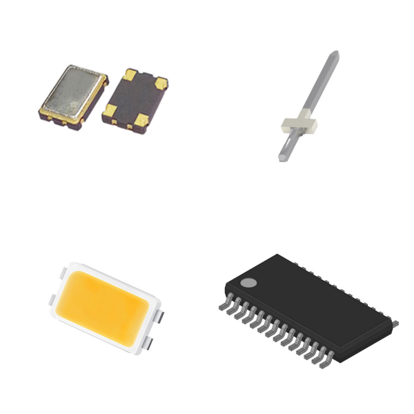
<h1> Uncategorized </h1> <p> Products that are not currently assigned to a family class will be temporarily assigned to the unclassified products in the uncategorized category. </p>